126
6. Double check all power has been removed from the biosafety cabinet.
7. Disconnect the two (2) wire harness connections from the motor. The 5-pin
connector, located closest to the blower, is released by depressing the locking
tabs on either side of the connector. The 16-pin data connector is released by
depressing the single locking tab in the center of the connector, on the side of the
connector closest to the blower. See Figure 12-38.
Note:
On a Type C1, it may be difficult to reach the two motor wiring connectors
described in Step 7. If this is the case, disconnect the exhaust motor wire harness at
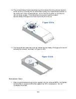
the pass-thru port near the top of the exhaust compartment. Once the exhaust plenum
is free from the biosafety cabinet, the two wire connectors can easily be disconnected
from the exhaust motor. See Figure 12-39.
Figure 12-38
5-pin
Connector
Locking Tabs
16-pin
Connector
Locking Tab
Motor
Blower
Figure 12-39
Summary of Contents for Logic+ A2
Page 149: ...149 208 240V...
Page 151: ...151 Blower only will not start...
Page 152: ...152 Lights only will not illuminate...
Page 153: ...153 UV Light will not illuminate...
Page 154: ...154 Airflow Alert activating...
Page 155: ...155 Filter Life Gauge not at 100 when new...
Page 156: ...156 Contamination in the work area...
Page 200: ...200 Figure 23 4 1 2 4 3 5 7 6 8 8...
Page 201: ...201 END OF 3849920 Figure 23 5 9 10 11 12 13...


