117
Blower/Motor Replacement
The motor(s) in the biosafety cabinet are ECM, brushless DC motors with extremely
high reliability. It is rare for the motor to fail. If the blower(s) fail to start, check all
possible causes first. The most likely cause for blower failure is a loose wire
connection. Another reason for accessing the blower/motor is a foreign object caught in
the blower wheel, or the blower wheel is out of balance.
The blower/motor assembly on a biosafety cabinet will be contaminated with
biohazardous material. Always assume the blower/motor is contaminated, even if you
are told the biosafety cabinet has not been used. For your safety, take all necessary
precautions before opening the blower/plenum cover, including: gaseous
decontamination of the biosafety cabinet, proper breathing, eye, and skin protection
from biohazards.
Type A2 (8, 9, 10-inch sash) & B2
If replacing a blower/motor assembly, the motor must be programmed at Labconco.
The blower/motor assembly must also be balanced by Labconco, and therefore it is
strongly recommended to replace the blower/motor assembly, never the motor or
blower individually. Failure to replace the blower/motor with a genuine Labconco
assembly will result in failed or incorrect operation, which can jeopardize the protection
the biosafety cabinet provides the operator, product, and lab environment.
Blower/motors can be awkward to handle, and the blower wheel may contain sharp
edges. Use safe lifting techniques when removing and replacing the blower/motor.
Always wear gloves and eye protection when handling a blower/motor assembly.
1. Thoroughly and properly decontaminate the biosafety cabinet.
2. Remove the front dress panel as described earlier in this section under
Removal
of External Dress Panels
. Unplug the power cord to this biosafety cabinet.
3. Loosen all of the Phillips screws around the perimeter of the blower/plenum
cover. Remove all screws except two along the top edge of the cover. This will
support the cover. The sash stop bracket is held in place by two of the
blower/plenum cover screws. Remove this bracket.
4.
A2 ONLY:
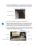
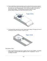
Release the damper seal (Figure 12-26) by pulling the outside edge of
the seal towards the bolt at the center, and then push the cover inside the
blower/plenum cover (Figure 12-27).
B2
– Skip Step 4, proceed to Step 5.
Summary of Contents for Logic+ A2
Page 149: ...149 208 240V...
Page 151: ...151 Blower only will not start...
Page 152: ...152 Lights only will not illuminate...
Page 153: ...153 UV Light will not illuminate...
Page 154: ...154 Airflow Alert activating...
Page 155: ...155 Filter Life Gauge not at 100 when new...
Page 156: ...156 Contamination in the work area...
Page 200: ...200 Figure 23 4 1 2 4 3 5 7 6 8 8...
Page 201: ...201 END OF 3849920 Figure 23 5 9 10 11 12 13...


