81
7. Place the thermal anemometer, now secured to the Labconco Holder, onto the
grille. The two pins in the Holder will drop into two holes on the grille. The
thermal anemometer probe should line up with the test point mark made earlier.
Start by placing the anemometer and Holder at the far left test point mark. See
Figure 10-33 for reference.
11. Start the blower(s), and let the cabinet operate for at least 5 minutes. After the
warm-up period expires, the biosafety cabinet will display a sash alarm. This is
because the sash is at the restricted height required for this test. Press
[OK/MUTE]
to silence the alarm for 5 minutes.
12. This test requires the anemometer to provide highly accurate results. Establish
the necessary correction factor to the thermal anemometer from its calibration
performance test in a calibrated wind tunnel. This should be available from the
calibration institution or company used to calibrate the thermal anemometer.
Calculate the thermal anemometer manufacturer’s recommended correction
factor(s) for conditions of temperature, humidity, barometric pressure, and
altitude.
13.
Set the anemometer’s time constant to 10-15 seconds for greater data stability.
14. Take one velocity reading at each of the marked test points.
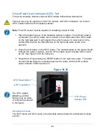
Figure 10-33
Thermal anemometer
probe in Holder
Summary of Contents for Logic+ A2
Page 149: ...149 208 240V...
Page 151: ...151 Blower only will not start...
Page 152: ...152 Lights only will not illuminate...
Page 153: ...153 UV Light will not illuminate...
Page 154: ...154 Airflow Alert activating...
Page 155: ...155 Filter Life Gauge not at 100 when new...
Page 156: ...156 Contamination in the work area...
Page 200: ...200 Figure 23 4 1 2 4 3 5 7 6 8 8...
Page 201: ...201 END OF 3849920 Figure 23 5 9 10 11 12 13...


