Step 4: Calibrate the Face Tool
KVAL Operation Manual
3-20
Note:
To help identify tools that need to be calibrated, view
Tool Path Review
.
“About the Tool Path Preview Test Tab” on page 3-20
Tip:
To help isolate tool function, use the
Tool Config
page to disable or enable sus
-
pected tools. After isolating the tool, run the
Door Job
late and Calibrate a Specific Router” on page 3-21
1.
Create a new
Door Job
of a
Lock Cut
of your choice.
2.
Add
Door Job
to the
Queue
.
3.
Once the cut is machined, measure the
length
,
width
, and
depth
positions of the cut.
If the cut is not in the specification, determine which tool and axis needs to be cali
-
brated.
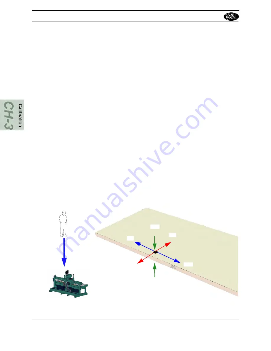
4.
Perform the
Left Hand Rule
pointed at the cut lock to determine axis direction. See
illustration below.
• If
diameters
of the plunges are out of specification, the
Diameter Offset
needs to
be adjusted.
• If the
length
of the cut is out of specification, the
X-Axis
needs to be adjusted.
• If the
width
of the cut is out of specification, the
Y-Axis
needs to be adjusted.
• If the
depth
cut is out of specification, the
Z-Axis
needs to be adjusted.
5.
If not in specification, adjust the location. Repeat until specification is reached.
Face Tools Calibration Reference Cut
The figure below, shows a sample reference cut and the type of offset to input into the calibration
menu.
See “How to Enter Calibration Data” on page 3-7
+
X
+
Y
+
Z
-
X
-
Z
-
Y
Summary of Contents for MLX
Page 59: ...About the Tool Config Tabs 2 29 KVAL MLX Operation Service Manual ...
Page 64: ...Description of the Light Tower KVAL MLX Operation Service Manual 2 34 ...
Page 90: ...System IT Administration KVAL MLX Operation Service Manual 4 4 ...
Page 117: ...Collet Torque Values 5 27 KVAL MLX Operation Service Manual ...
Page 118: ...Collet Torque Values KVAL MLX Operation Service Manual 5 28 ...
Page 141: ......
Page 142: ......
Page 143: ......


