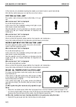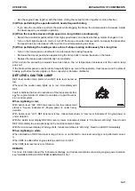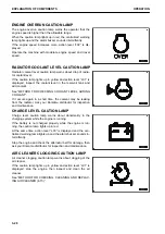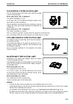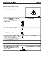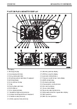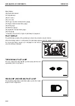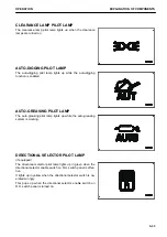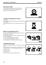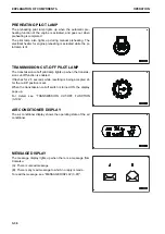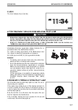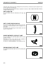
WARNING DISPLAY
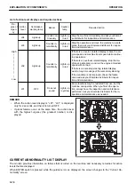
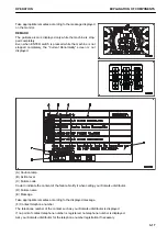
The caution lamps displayed on the warning display section are
as follows. Take appropriate measures according to the speci-
fied remedies.
REMARK
• When 1 type of alarm is generated, it is displayed on cau-
tion lamp (A).
• When 2 types of alarm are generated, they are displayed
on caution lamps (A) and (B).
• When 3 types of alarm are generated, they are displayed
on caution lamps (A) and (B) alternately at intervals of 2
seconds.
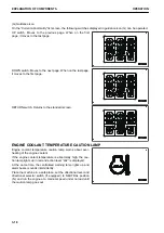
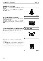
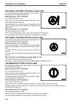
STEERING SYSTEM CAUTION LAMP
The steering system caution lamp warns about abnormality in
the steering system.
If the caution lamp lights up in yellow and action level “L01” is
displayed, always perform inspection and maintenance after
the operation is finished.
Ask your Komatsu distributor for the inspection and mainte-
nance as needed.
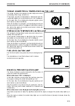
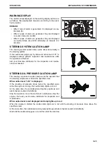
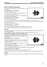
STEERING OIL PRESSURE CAUTION LAMP
The steering oil pressure caution lamp warns the operator that
the steering oil pressure is below the specified value.
When action level “L03” is displayed
If the steering oil pressure drops below the specified value
while the engine is running, the caution lamp lights up in red.
At the same time, the centralized warning lamp lights up and
alarm buzzer sounds intermittently.
Stop the operation, move the machine to a safe place, stop the
engine, then ask your Komatsu distributor for inspection and
maintenance.
When action level is not displayed and lamp lights up in red
When the engine is started, the caution lamp lights up in red until the steering oil pressure rises above the
specified value.
At the same time, the centralized warning lamp lights up and alarm buzzer sounds intermittently.
Wait until the caution lamp goes out, and then start the machine.
OPERATION
EXPLANATION OF COMPONENTS
3-23
Summary of Contents for WA480-8
Page 2: ......
Page 19: ...Distributor name Address Phone Fax Service personnel FOREWORD PRODUCT INFORMATION 1 17...
Page 29: ...LOCATION OF SAFETY LABELS SAFETY SAFETY LABELS 2 3...
Page 159: ...SWITCHES 1 ECSS switch 2 Front working lamp switch OPERATION EXPLANATION OF COMPONENTS 3 91...
Page 302: ...Securing position Fixing angle A 61 B 53 C 33 D 38 TRANSPORTATION OPERATION 3 234...
Page 324: ......
Page 397: ...Viewed from the rear side of the machine MAINTENANCE MAINTENANCE PROCEDURE 4 73...
Page 402: ......
Page 403: ...SPECIFICATIONS 5 1...
Page 406: ......
Page 422: ......
Page 423: ...REPLACEMENT PARTS 7 1...
Page 439: ......


