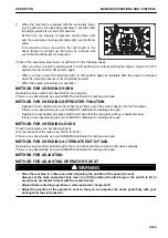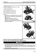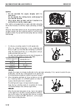
Install the mirror to a position where you can easily see the
hatched area in the figure.
The reference values of the visibility range are as follows.
Visibility range (left): 3400 mm
Visibility range (right): 3400 mm
Mirror A: Hatched area (a) must be in view.
Mirror B: Hatched area (b) must be in view.
Mirror C: Hatched area (c) must be in view.
Mirror D: Hatched area (d) must be in view.
NOTICE
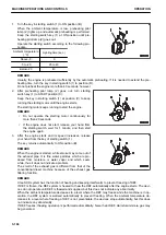
• Tighten the mirror mounting bolts securely to prevent
the mirrors from coming off due to loosening of the
bolt.
Tightening torque
Mirrors A, B: 3 ± 0.5 Nm {0.3 ± 0.05 kgm}
Mirrors C, D: 15.7 to 18.6 Nm {1.6 to 1.9 kgm}
• If the torque cannot be controlled, ask your Komatsu
distributor for adjustment.
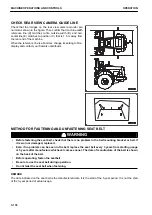
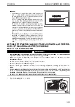
METHOD FOR ADJUSTING REAR VIEW CAMERA
METHOD FOR ADJUSTING REAR VIEW CAMERA ANGLE
k
k
WARNING
• Be sure to adjust the camera before starting work. If it is not adjusted properly, you cannot secure
the visibility and a serious personal injury or death may result.
• When adjusting the camera, if you stand on an unstable place, or take an unstable posture, you may
fall and be injured. Put proper stepladder or step on the level and firm ground, and adjust the cam-
era in secure posture.
• Install only the Komatsu genuine camera.
OPERATION
MACHINE OPERATIONS AND CONTROLS
3-175
Summary of Contents for WA480-8
Page 2: ......
Page 19: ...Distributor name Address Phone Fax Service personnel FOREWORD PRODUCT INFORMATION 1 17...
Page 29: ...LOCATION OF SAFETY LABELS SAFETY SAFETY LABELS 2 3...
Page 159: ...SWITCHES 1 ECSS switch 2 Front working lamp switch OPERATION EXPLANATION OF COMPONENTS 3 91...
Page 302: ...Securing position Fixing angle A 61 B 53 C 33 D 38 TRANSPORTATION OPERATION 3 234...
Page 324: ......
Page 397: ...Viewed from the rear side of the machine MAINTENANCE MAINTENANCE PROCEDURE 4 73...
Page 402: ......
Page 403: ...SPECIFICATIONS 5 1...
Page 406: ......
Page 422: ......
Page 423: ...REPLACEMENT PARTS 7 1...
Page 439: ......

