


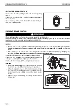


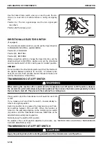


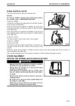


The work equipment lock switch (1) is a device used to lock the
operation of the work equipment.
Keep pulling the lock (2) of switch in the direction (b) shown by
arrow and push it into the direction (c).
The switch automatically returns to its original position when re-
leasing your hand from the switch.
The work equipment is locked (the pilot lamp lights up) or un-
locked (the pilot lamp goes out) each time you push the switch
into the direction (c).
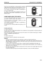
Even if you may turn the starting switch to OFF position with
the work equipment unlocked (pilot lamp goes out), the work
equipment is locked (pilot lamp lights up) if you turn the starting
switch to ON position again.
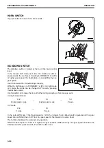
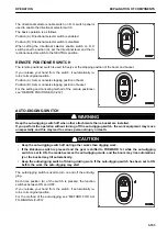
GEAR SPEED SWITCH
The gear speed switch is used to change the gear speed of the machine.
MANUAL SHIFT
A desired gear speed can be selected from the 4 forward and 4
reverse gear speeds by turning the gear speed switch to that
gear speed position.
Use the 1st and 2nd gear speeds for work and the 3rd and 4th
for travel.
Position (a): 1st speed
Position (b): 2nd speed
Position (c): 3rd speed
Position (d): 4th speed
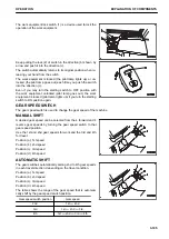
AUTOMATIC SHIFT
The gear switches automatically among 2nd to 4th gear speeds
in each travel direction, depending on the travel condition.
Position (a): 1st speed
Position (b): 2nd speed
Position (c): 3rd speed
Position (d): 4th speed
The table shows the range of the gear speed that is automati-
cally shift by the gear speed switch position.
Gear speed switch position
Gear speed
2nd
1st
⇔
2nd
3rd
1st
⇔
2nd
⇔
3rd
4th
1st
⇔
2nd
⇔
3rd
⇔
4th
OPERATION
EXPLANATION OF COMPONENTS
3-105
Summary of Contents for WA480-8
Page 2: ......
Page 19: ...Distributor name Address Phone Fax Service personnel FOREWORD PRODUCT INFORMATION 1 17...
Page 29: ...LOCATION OF SAFETY LABELS SAFETY SAFETY LABELS 2 3...
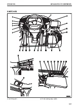
Page 159: ...SWITCHES 1 ECSS switch 2 Front working lamp switch OPERATION EXPLANATION OF COMPONENTS 3 91...
Page 302: ...Securing position Fixing angle A 61 B 53 C 33 D 38 TRANSPORTATION OPERATION 3 234...
Page 324: ......
Page 397: ...Viewed from the rear side of the machine MAINTENANCE MAINTENANCE PROCEDURE 4 73...
Page 402: ......
Page 403: ...SPECIFICATIONS 5 1...
Page 406: ......
Page 422: ......
Page 423: ...REPLACEMENT PARTS 7 1...
Page 439: ......


