
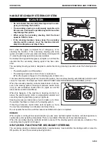


REMOTE POSITIONER
This machine has the functions of the remote bucket positioner and the remote boom positioner.
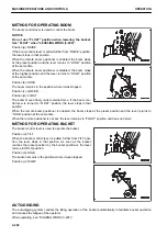
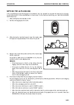
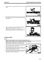
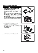
METHOD FOR OPERATING REMOTE BUCKET POSITIONER
1.
Raise the boom and dump the bucket.
2.
Operate the bucket control lever to the tilt detent position
and release your hand from the lever.
The bucket tilts and then its tilting stops at the moment
when the bucket control lever returns from the detent posi-
tion to the HOLD position.
When the boom is lowered near to the ground, the bucket
cutting edge is set to the position specified by remote posi-
tioner switch (1).
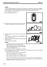
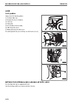
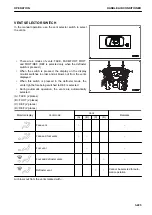
3.
To change the bucket stop position, stop the bucket at a
desired position and press position (b) of switch (1).
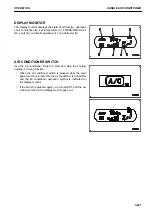
The buzzer “beeps” and the bucket stop position is set to
that position. And the monitor displays the position setup
level.
When resetting the bucket stop position, hold down posi-
tion (b) of switch (1) for more than 1 second.
The buzzer “beeps” indicating that the bucket stop position
so far set has been reset. The position is then returned to
the level position A, B or C that has been specified from
“Bucket Level Position Selection”.
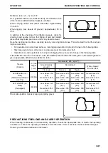
REMARK
The bucket stop position can be set within the range of ±5
steps of A, B or C that has been set in “Bucket Level Posi-
tion Selection”.
The bucket stop position cannot be set beyond this range.
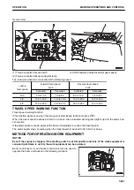
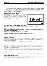
The table below shows the relationship between the angle setup level and bucket stop angle of the standard
bucket.
Angle setup level
-5
-4
-3
-2
-1
0
1
2
3
4
5
Bucket stop angle
-5
-4
-3
-2
-1
0
1
2
3
4
5
(The bucket stop angle is a rough indication.)
MACHINE OPERATIONS AND CONTROLS
OPERATION
3-212
Summary of Contents for WA480-8
Page 2: ......
Page 19: ...Distributor name Address Phone Fax Service personnel FOREWORD PRODUCT INFORMATION 1 17...
Page 29: ...LOCATION OF SAFETY LABELS SAFETY SAFETY LABELS 2 3...
Page 159: ...SWITCHES 1 ECSS switch 2 Front working lamp switch OPERATION EXPLANATION OF COMPONENTS 3 91...
Page 302: ...Securing position Fixing angle A 61 B 53 C 33 D 38 TRANSPORTATION OPERATION 3 234...
Page 324: ......
Page 397: ...Viewed from the rear side of the machine MAINTENANCE MAINTENANCE PROCEDURE 4 73...
Page 402: ......
Page 403: ...SPECIFICATIONS 5 1...
Page 406: ......
Page 422: ......
Page 423: ...REPLACEMENT PARTS 7 1...
Page 439: ......


