


ENGINE TECHNOLOGY TO CONFORM EXHAUST GAS
EMISSION
About Engine Technology
This engine technology combines a Komatsu Diesel Particulate Filter (KDPF) and Komatsu’s Urea Selective
Catalytic Reduction (SCR) to conform EU Stage IV emission regulation in the European Union.
• Komatsu Diesel Particulate Filter (KDPF): A device which captures diesel particular matter or soot in the
exhaust gas to purify exhaust gas. If soot is accumulated to a certain level in the filter, a purification process
to burn the soot is performed automatically to keep the filtering performance of KDPF high.
• Komatsu’s Urea SCR system: A device which decomposes the toxic nitrogen oxides (NOx) mixed in the
exhaust gas into harmless nitrogen and water. Spraying the reagent (Diesel Exhaust Fluid) into the exhaust
gas produces a reaction between the nitrogen oxides and ammonia generated from the urea solution and
decomposes the nitrogen oxides into nitrogen and water.
About Diesel Exhaust Fluid (DEF)
Diesel Exhaust Fluid is the reagent for the SCR system.
DEF is the abbreviation for Diesel Exhaust Fluid, and is represented as DEF throughout this manual.
DEF is a colorless transparent and aqueous urea solution made with 32.5 % urea (AUS32) and 67.5 % deion-
ized water. Urea as main constituent is a material which is used for cosmetics, medical and pharmaceutical
products, and fertilizer, etc.
Commercial DEF, commonly referred to as AdBlue
®
in the European Union, that quality standards are main-
tained in accordance with DIN70070 and ISO 22241-1, to be used.
AdBlue
®
is a registered trade-mark of VDA (Verband der Automobilindustrie e.V.: Automobile Association of
Germany).
FOREWORD
ENGINE TECHNOLOGY TO CONFORM EXHAUST GAS EMISSION
1-13
Summary of Contents for WA480-8
Page 2: ......
Page 19: ...Distributor name Address Phone Fax Service personnel FOREWORD PRODUCT INFORMATION 1 17...
Page 29: ...LOCATION OF SAFETY LABELS SAFETY SAFETY LABELS 2 3...
Page 159: ...SWITCHES 1 ECSS switch 2 Front working lamp switch OPERATION EXPLANATION OF COMPONENTS 3 91...
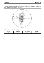
Page 302: ...Securing position Fixing angle A 61 B 53 C 33 D 38 TRANSPORTATION OPERATION 3 234...
Page 324: ......
Page 397: ...Viewed from the rear side of the machine MAINTENANCE MAINTENANCE PROCEDURE 4 73...
Page 402: ......
Page 403: ...SPECIFICATIONS 5 1...
Page 406: ......
Page 422: ......
Page 423: ...REPLACEMENT PARTS 7 1...
Page 439: ......


