


Section 8
Electrical System
20412989
1-2012/Rev 08
8-7
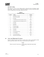
Table 8-1
Sensors and Solenoids
Component
Function
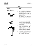
Hydraulic Reservoir
5
The temperature/low level switch monitors the oil
temperature and level in the reservoir. Although the
float switch and the temperature switch are combined
in a single unit, the two switches function
independently.
If the operating oil temperature exceeds 144
F (62
C) an automatic shutdown occurs. If the hydraulic
fluid level falls below specifications, a low oil level
shutdown occurs.
6
Models equipped with an air cooler utilize a
temperature switch to regulate oil temperature.
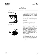
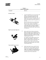
Hydraulic Manifold
7
The 4-way directional control valve shifts the
hydraulics back and forth to the intensifier. A shift
valve directs pressurized oil to one end of the
hydraulic cylinder and returns fluid to the reservoir
from the opposite end, causing the intensifier to
stroke. The movement is controlled hydraulically by
a pilot valve that is electronically operated by two
solenoids, energized by the PLC. As power is
directed from one solenoid to the other, LEDs are
alternately illuminated.
8
When low pressure is selected, a normally closed,
solenoid valve is activated. The valve remains
closed while operating in high pressure and is held
open electrically during low pressure operation. An
illuminated LED on the solenoid indicates low
pressure operation.
Summary of Contents for Streamline SL-V 100 Plus
Page 60: ...Section 4 Operation 20412948 8 2012 Rev 04 4 19 Figure 4 20 Language Screen ...
Page 179: ...Section 12 Parts List 20413146 8 2012 Rev 12 12 7 Figure 12 2 Intensifier Assembly ...
Page 185: ...Section 12 Parts List 20413146 8 2012 Rev 12 12 13 Figure 12 6 Hydraulic Piston Assembly ...
Page 187: ...Section 12 Parts List 20413146 8 2012 Rev 12 12 15 Figure 12 7 High Pressure Piping ...
Page 191: ...Section 12 Parts List 20413146 8 2012 Rev 12 12 19 Figure 12 9 Hydraulic Power Package ...
Page 193: ...Section 12 Parts List 20413146 8 2012 Rev 12 12 21 Figure 12 10 Motor Pump Assembly ...
Page 195: ...Section 12 Parts List 20413146 8 2012 Rev 12 12 23 Figure 12 11 Hydraulic Manifold Assembly ...
Page 197: ...Section 12 Parts List 20413146 8 2012 Rev 12 12 25 Figure 12 12 Hydraulic Hose Connections ...
Page 199: ...Section 12 Parts List 20413146 8 2012 Rev 12 12 27 Figure 12 13 Reservoir Assembly ...
Page 202: ...Section 12 Parts List 20413146 8 2012 Rev 12 12 30 Figure 12 14 Bulkhead Pipe Assembly ...
Page 203: ......
Page 205: ...Section 12 Parts List 20413146 8 2012 Rev 12 12 32 Figure 12 15 Cover Assembly ...
Page 207: ...Section 12 Parts List 20413146 8 2012 Rev 12 12 34 Figure 12 16 Electrical Assembly ...
Page 210: ...Section 12 Parts List 20413146 8 2012 Rev 12 12 37 Figure 12 17 Controls Subassembly ...
Page 211: ......
Page 217: ...Section 12 Parts List 20413146 8 2012 Rev 12 12 43 Figure 12 20 Proportional Pressure Control ...
Page 219: ...Section 12 Parts List 20413146 8 2012 Rev 12 12 45 Figure 12 21 High Pressure Transducer ...
Page 221: ...Section 12 Parts List 20413146 8 2012 Rev 12 12 47 Figure 12 22 Redundant Kit ...
Page 250: ......
Page 251: ......
Page 252: ......
Page 253: ......
Page 254: ......
Page 255: ......
Page 256: ......
Page 257: ......
Page 258: ......
Page 259: ......
Page 260: ......