


20412997
8-2012/Rev 12
9-1
SECTION 9
HIGH PRESSURE WATER SYSTEM
9.1
Overview
The high pressure water system is supported by both the cutting water supply circuit and the
hydraulic circuit. Cutting water of sufficient flow and pressure is routed from the cutting water
supply circuit to the intensifier where it is pressurized up to 60,000 psi (4,137 bar) and delivered
to the cutting head.
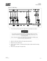
The directional control valve in the hydraulic system creates the stroking action of the intensifier
by sending pressurized hydraulic oil to one side of the hydraulic cylinder or the other. As the
flow is sent to one side, hydraulic fluid is returned to the reservoir from the opposite side.
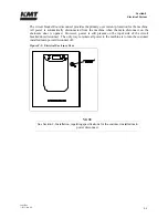
Figure 9-1: High Pressure Water System Circuit
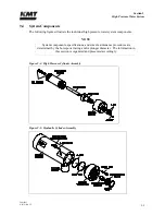
System components include a double-ended hydraulic cylinder; reciprocating piston assembly;
high pressure cylinders attached to each end of the hydraulic cylinder; two plungers, sealing
heads and hard seal end caps; one or two liter capacity attenuators, and a safety dump valve.
Sophisticated check valves and seal assemblies ensure hydraulic oil, and the low pressure and
high pressure water travel in the appropriate direction. Warning and shutdown sensors monitor
strategic pressure, temperature and fluid levels to safeguard against component damage.
Summary of Contents for Streamline SL-V 100 Plus
Page 60: ...Section 4 Operation 20412948 8 2012 Rev 04 4 19 Figure 4 20 Language Screen ...
Page 179: ...Section 12 Parts List 20413146 8 2012 Rev 12 12 7 Figure 12 2 Intensifier Assembly ...
Page 185: ...Section 12 Parts List 20413146 8 2012 Rev 12 12 13 Figure 12 6 Hydraulic Piston Assembly ...
Page 187: ...Section 12 Parts List 20413146 8 2012 Rev 12 12 15 Figure 12 7 High Pressure Piping ...
Page 191: ...Section 12 Parts List 20413146 8 2012 Rev 12 12 19 Figure 12 9 Hydraulic Power Package ...
Page 193: ...Section 12 Parts List 20413146 8 2012 Rev 12 12 21 Figure 12 10 Motor Pump Assembly ...
Page 195: ...Section 12 Parts List 20413146 8 2012 Rev 12 12 23 Figure 12 11 Hydraulic Manifold Assembly ...
Page 197: ...Section 12 Parts List 20413146 8 2012 Rev 12 12 25 Figure 12 12 Hydraulic Hose Connections ...
Page 199: ...Section 12 Parts List 20413146 8 2012 Rev 12 12 27 Figure 12 13 Reservoir Assembly ...
Page 202: ...Section 12 Parts List 20413146 8 2012 Rev 12 12 30 Figure 12 14 Bulkhead Pipe Assembly ...
Page 203: ......
Page 205: ...Section 12 Parts List 20413146 8 2012 Rev 12 12 32 Figure 12 15 Cover Assembly ...
Page 207: ...Section 12 Parts List 20413146 8 2012 Rev 12 12 34 Figure 12 16 Electrical Assembly ...
Page 210: ...Section 12 Parts List 20413146 8 2012 Rev 12 12 37 Figure 12 17 Controls Subassembly ...
Page 211: ......
Page 217: ...Section 12 Parts List 20413146 8 2012 Rev 12 12 43 Figure 12 20 Proportional Pressure Control ...
Page 219: ...Section 12 Parts List 20413146 8 2012 Rev 12 12 45 Figure 12 21 High Pressure Transducer ...
Page 221: ...Section 12 Parts List 20413146 8 2012 Rev 12 12 47 Figure 12 22 Redundant Kit ...
Page 250: ......
Page 251: ......
Page 252: ......
Page 253: ......
Page 254: ......
Page 255: ......
Page 256: ......
Page 257: ......
Page 258: ......
Page 259: ......
Page 260: ......