


Section 9
High Pressure Water System
20412997
8-2012/Rev 12
9-13
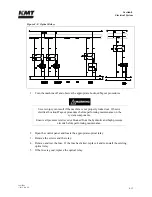
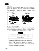
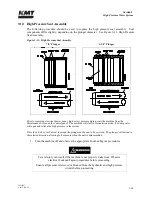
NOTE
An alignment mark is located on the hydraulic cylinder head under the KMT logo.
To ensure the high pressure cylinder is properly tightened and fully seated in the
hydraulic cylinder head, it is recommended that a corresponding mark be placed on
the high pressure cylinder after installation. Periodically inspect the cylinder for
movement. If movement is detected, retighten the assembly.
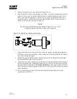
4.
Connect the high and low pressure water piping, following the procedure, High and Low
Pressure Water Piping.
5.
Start the machine in low pressure mode to flush air from the high pressure components
and to check for obvious leaks. After 5-10 strokes, switch to high pressure operation and
check for leaks.
If leaks are detected, turn the machine off and remedy the problem. When the problem
has been remedied, repeat the start up procedure, moving from low to high pressure soon
after the intensifier starts pumping water. There is no further need to flush air from the
system.
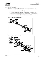
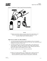
High Pressure Cylinder Maintenance
The plunger seal area in the high pressure cylinder bore should be inspected and cleaned each
time the high pressure seal assembly is replaced.
1.
Clean the sealing area on the inside diameter of the high pressure cylinder and inspect the
bore for rings, scratches, pits, residue or other potential leak paths.
2.
Seal material or residue can build up, forming a ring. Running a fingernail across the
buildup will cause it to appear as a surface flaw. Grooves or ridges are typically seal
debris buildup rather than marks on the inside diameter wall of the cylinder.
3.
Polish the inside diameter of the cylinder where the seal will locate with 600-grit wet/dry
sandpaper. Hold the sandpaper on the end of your finger and move in a cylindrical wiping
motion. Polish in a circumferential motion only. Do not polish or drag the sandpaper
along the length of the cylinder.
4.
Clean the residue from the inside diameter of the cylinder and re-inspect for surface
defects.
Summary of Contents for Streamline SL-V 100 Plus
Page 60: ...Section 4 Operation 20412948 8 2012 Rev 04 4 19 Figure 4 20 Language Screen ...
Page 179: ...Section 12 Parts List 20413146 8 2012 Rev 12 12 7 Figure 12 2 Intensifier Assembly ...
Page 185: ...Section 12 Parts List 20413146 8 2012 Rev 12 12 13 Figure 12 6 Hydraulic Piston Assembly ...
Page 187: ...Section 12 Parts List 20413146 8 2012 Rev 12 12 15 Figure 12 7 High Pressure Piping ...
Page 191: ...Section 12 Parts List 20413146 8 2012 Rev 12 12 19 Figure 12 9 Hydraulic Power Package ...
Page 193: ...Section 12 Parts List 20413146 8 2012 Rev 12 12 21 Figure 12 10 Motor Pump Assembly ...
Page 195: ...Section 12 Parts List 20413146 8 2012 Rev 12 12 23 Figure 12 11 Hydraulic Manifold Assembly ...
Page 197: ...Section 12 Parts List 20413146 8 2012 Rev 12 12 25 Figure 12 12 Hydraulic Hose Connections ...
Page 199: ...Section 12 Parts List 20413146 8 2012 Rev 12 12 27 Figure 12 13 Reservoir Assembly ...
Page 202: ...Section 12 Parts List 20413146 8 2012 Rev 12 12 30 Figure 12 14 Bulkhead Pipe Assembly ...
Page 203: ......
Page 205: ...Section 12 Parts List 20413146 8 2012 Rev 12 12 32 Figure 12 15 Cover Assembly ...
Page 207: ...Section 12 Parts List 20413146 8 2012 Rev 12 12 34 Figure 12 16 Electrical Assembly ...
Page 210: ...Section 12 Parts List 20413146 8 2012 Rev 12 12 37 Figure 12 17 Controls Subassembly ...
Page 211: ......
Page 217: ...Section 12 Parts List 20413146 8 2012 Rev 12 12 43 Figure 12 20 Proportional Pressure Control ...
Page 219: ...Section 12 Parts List 20413146 8 2012 Rev 12 12 45 Figure 12 21 High Pressure Transducer ...
Page 221: ...Section 12 Parts List 20413146 8 2012 Rev 12 12 47 Figure 12 22 Redundant Kit ...
Page 250: ......
Page 251: ......
Page 252: ......
Page 253: ......
Page 254: ......
Page 255: ......
Page 256: ......
Page 257: ......
Page 258: ......
Page 259: ......
Page 260: ......