Section 9
High Pressure Water System
20412997
8-2012/Rev 12
9-26
8.
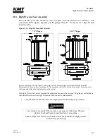
Thoroughly clean the bushing retainer flange, including the cross-drilled weep holes.
Install the retainer flange over the plunger.
9.
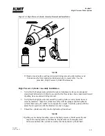
Install the retaining ring, ensuring the retaining ring fully seats inside the groove in the
hydraulic cylinder head.
The o-rings on the hydraulic cartridge will take up clearance. Tap lightly on the bushing
retainer flange with the plunger removal tool to compress the o-rings enough to start the
retaining ring in the groove. Use a flat blade screwdriver to push on the outer edge of the
retainer flange while working one end of the retaining ring into the groove. The retainer
flange should tilt or tip enough to allow the retaining ring to move into the groove.
Continue working the ring into the groove while tilting the retainer flange until the ring is
fully seated.
10.
Install the high pressure cylinder assembly into the hydraulic cylinder head, following the
procedure, High Pressure Cylinder Assembly Installation.
11.
Connect the high and low pressure water piping and turn the low pressure water supply
on.
9.12
Hydraulic Piston
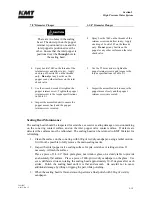
Two bearing rings provide wear contact between the piston and the inside diameter of the
hydraulic cylinder. On each end of the piston, six retainer pins hold the plunger in position. The
plunger retainer pins are held in place by a flat snap ring. Two internal check valves vent
unwanted hydraulic pressure from one side of the piston to the other, preventing pressure from
building behind the plunger button.
Figure 9-19: Hydraulic Piston Components
Summary of Contents for Streamline SL-V 100 Plus
Page 60: ...Section 4 Operation 20412948 8 2012 Rev 04 4 19 Figure 4 20 Language Screen ...
Page 179: ...Section 12 Parts List 20413146 8 2012 Rev 12 12 7 Figure 12 2 Intensifier Assembly ...
Page 185: ...Section 12 Parts List 20413146 8 2012 Rev 12 12 13 Figure 12 6 Hydraulic Piston Assembly ...
Page 187: ...Section 12 Parts List 20413146 8 2012 Rev 12 12 15 Figure 12 7 High Pressure Piping ...
Page 191: ...Section 12 Parts List 20413146 8 2012 Rev 12 12 19 Figure 12 9 Hydraulic Power Package ...
Page 193: ...Section 12 Parts List 20413146 8 2012 Rev 12 12 21 Figure 12 10 Motor Pump Assembly ...
Page 195: ...Section 12 Parts List 20413146 8 2012 Rev 12 12 23 Figure 12 11 Hydraulic Manifold Assembly ...
Page 197: ...Section 12 Parts List 20413146 8 2012 Rev 12 12 25 Figure 12 12 Hydraulic Hose Connections ...
Page 199: ...Section 12 Parts List 20413146 8 2012 Rev 12 12 27 Figure 12 13 Reservoir Assembly ...
Page 202: ...Section 12 Parts List 20413146 8 2012 Rev 12 12 30 Figure 12 14 Bulkhead Pipe Assembly ...
Page 203: ......
Page 205: ...Section 12 Parts List 20413146 8 2012 Rev 12 12 32 Figure 12 15 Cover Assembly ...
Page 207: ...Section 12 Parts List 20413146 8 2012 Rev 12 12 34 Figure 12 16 Electrical Assembly ...
Page 210: ...Section 12 Parts List 20413146 8 2012 Rev 12 12 37 Figure 12 17 Controls Subassembly ...
Page 211: ......
Page 217: ...Section 12 Parts List 20413146 8 2012 Rev 12 12 43 Figure 12 20 Proportional Pressure Control ...
Page 219: ...Section 12 Parts List 20413146 8 2012 Rev 12 12 45 Figure 12 21 High Pressure Transducer ...
Page 221: ...Section 12 Parts List 20413146 8 2012 Rev 12 12 47 Figure 12 22 Redundant Kit ...
Page 250: ......
Page 251: ......
Page 252: ......
Page 253: ......
Page 254: ......
Page 255: ......
Page 256: ......
Page 257: ......
Page 258: ......
Page 259: ......
Page 260: ......

