


Section 11
Specifications
20413013
8-2012/Rev 10
11-11
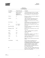
11.6
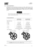
Torque Specifications
Measurements are made with lubricated components and a certified, calibrated torque wrench.
Inconsistencies in wrench settings, lubrication and technique may not produce a leak free seal. If
leakage occurs, the torque can be increased to seal the components. However,
do not exceed the
recommended torque value by more than 15 percent
. If leakage persists, there is a component
problem.
Excessive torque can cause component damage or failure, resulting in potential
hazards to equipment and personnel.
Torque Specifications
7/8 inch (22 mm)
Diameter Plunger
1-1/8 inch (29 mm)
Diameter Plunger
Hard Seal End Cap
Jackbolts
6 (7/16”) each
8 (7/16”) each
1st Stage
Hand Tight
Hand Tight
2nd Stage
20 ft-lbs (27 Nm)
Crossing Pattern
20 ft-lbs (27 Nm)
Crossing Pattern
3rd Stage
32-35 ft-lbs (43-47 Nm)
*
Crossing Pattern
32-35 ft-lbs (43-47 Nm)
*
Crossing Pattern
4th Stage
32-35 ft-lbs (43-47 Nm)
*
Clockwise Pattern From Bolt 1
32-35 ft-lbs (43-47 Nm)
*
Clockwise Pattern From Bolt 1
Socket Wrench Size
3/8 inch
3/8 inch
6-Bolt Crossing Pattern
8-Bolt Crossing Pattern
* Note:
A maximum torque of 38 ft-lbs (51 Nm) is etched on the hard seal end cap. This represents
the
maximum
allowable torque, not the recommended torque.
Summary of Contents for Streamline SL-V 100 Plus
Page 60: ...Section 4 Operation 20412948 8 2012 Rev 04 4 19 Figure 4 20 Language Screen ...
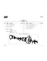
Page 179: ...Section 12 Parts List 20413146 8 2012 Rev 12 12 7 Figure 12 2 Intensifier Assembly ...
Page 185: ...Section 12 Parts List 20413146 8 2012 Rev 12 12 13 Figure 12 6 Hydraulic Piston Assembly ...
Page 187: ...Section 12 Parts List 20413146 8 2012 Rev 12 12 15 Figure 12 7 High Pressure Piping ...
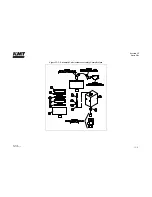
Page 191: ...Section 12 Parts List 20413146 8 2012 Rev 12 12 19 Figure 12 9 Hydraulic Power Package ...
Page 193: ...Section 12 Parts List 20413146 8 2012 Rev 12 12 21 Figure 12 10 Motor Pump Assembly ...
Page 195: ...Section 12 Parts List 20413146 8 2012 Rev 12 12 23 Figure 12 11 Hydraulic Manifold Assembly ...
Page 197: ...Section 12 Parts List 20413146 8 2012 Rev 12 12 25 Figure 12 12 Hydraulic Hose Connections ...
Page 199: ...Section 12 Parts List 20413146 8 2012 Rev 12 12 27 Figure 12 13 Reservoir Assembly ...
Page 202: ...Section 12 Parts List 20413146 8 2012 Rev 12 12 30 Figure 12 14 Bulkhead Pipe Assembly ...
Page 203: ......
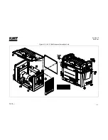
Page 205: ...Section 12 Parts List 20413146 8 2012 Rev 12 12 32 Figure 12 15 Cover Assembly ...
Page 207: ...Section 12 Parts List 20413146 8 2012 Rev 12 12 34 Figure 12 16 Electrical Assembly ...
Page 210: ...Section 12 Parts List 20413146 8 2012 Rev 12 12 37 Figure 12 17 Controls Subassembly ...
Page 211: ......
Page 217: ...Section 12 Parts List 20413146 8 2012 Rev 12 12 43 Figure 12 20 Proportional Pressure Control ...
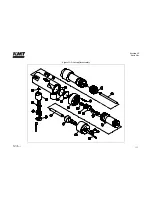
Page 219: ...Section 12 Parts List 20413146 8 2012 Rev 12 12 45 Figure 12 21 High Pressure Transducer ...
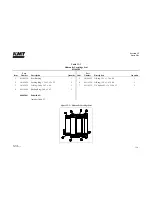
Page 221: ...Section 12 Parts List 20413146 8 2012 Rev 12 12 47 Figure 12 22 Redundant Kit ...
Page 250: ......
Page 251: ......
Page 252: ......
Page 253: ......
Page 254: ......
Page 255: ......
Page 256: ......
Page 257: ......
Page 258: ......
Page 259: ......
Page 260: ......