background image


Section 8 

Electrical System 


20412989 
1-2012/Rev 08 

8-9 


Table 8-1 

Sensors and Solenoids 

Component  

Function 


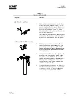
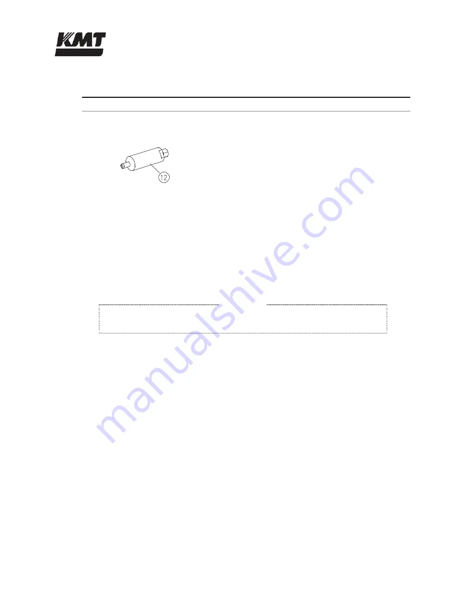
Pressure Transducer 


12 

The optional pressure transducer reads the output 
pressure from the attenuator in the high pressure 
system.  A signal is sent to the PLC module that 
allows the operating pressure to be viewed from the 
control panel. 


Softstarter 

The softstarter is a reduced voltage starter that minimizes system mechanical and electrical stress 
by reducing current surges.  A 

RUN

/

FAULT

 LED display relays device status information and fault 

diagnostics.  A flashing red LED indicates a fault, either internal to the softstarter, or with the 
incoming power or motor.  The number of flashes in sequence, indicates the fault, see Section 10, 
Troubleshooting. 

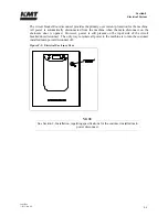
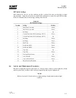
 NOTE  

The blue arrow selector above the LED display is the setting for full load amps.  

The arrow must be set at the FLA for the motor. 


Summary of Contents for Streamline SL-V 100 Plus

Page 1: ...MANUAL 20413130 R13 STREAMLINE SL V 100 PLUS WATERJET INTENSIFIER OPERATION AND MAINTENANCE MANUAL ...

Page 2: ...es the information described in this manual to be accurate and reliable Much care has been taken in its preparation however the Company cannot accept any responsibility financial or otherwise for any consequences arising out of the use of this material The information contained herein is subject to change and revisions may be issued advising of such changes and or additions KMT WATERJET SYSTEMS 20...

Page 3: ...edure 1 5 Warning Labels 1 6 Emergency Medical Treatment 1 8 1 5 Worldwide Product Support 1 8 1 6 Spare Parts 1 9 1 7 Manual Organization 1 9 1 8 Equipment and Service Manual Questionnaire 1 10 2 Installation 2 1 2 1 Overview 2 1 2 2 Installation Summary 2 1 2 3 Site Requirements 2 2 Transporting 2 3 2 4 Power Requirements 2 4 2 5 Service Connections 2 5 Cooling Water Oil to Water Models 2 6 Cutt...

Page 4: ...ce 4 2 Startup after Motor Stop 4 2 Startup after Emergency Stop 4 2 4 3 Display Controls 4 3 4 4 Main Menu 4 4 4 5 Run Screens 4 5 4 6 Pressure Control Screen 4 6 4 7 Setup Screens 4 7 4 8 Stroke Rate Screens 4 8 4 9 Hours Screens 4 10 4 10 Run Screen Alarms 4 11 4 11 Alarm Banners 4 13 4 12 Alarms Screen 4 14 Installing a New Battery 4 16 4 13 Alarm History 4 16 Changing the Date and Time 4 17 4...

Page 5: ...ntenance 7 6 Motor Maintenance 7 6 Flexible Coupling Replacement 7 7 Hydraulic Compensator Maintenance 7 9 Hydraulic Pump or Electric Motor Replacement 7 12 Hydraulic Oil Replacement 7 16 Electric Motor Bump 7 17 8 Electrical System 8 1 8 1 Overview 8 1 8 2 Optional System Components 8 1 8 3 Operation 8 2 Sensors and Solenoids 8 5 Softstarter 8 9 8 4 Service and Maintenance Procedures 8 10 Proximi...

Page 6: ...9 26 Hydraulic Piston Removal 9 27 Bearing Rings and Seal Assembly 9 28 Plunger Button Sockets Seals and Retainer Pins 9 28 Internal Check Valves 9 29 Hydraulic Piston Installation 9 30 9 13 Hydraulic Cylinder Maintenance 9 31 9 14 High Pressure Attenuator 9 31 9 15 High Pressure Dump Valve 9 32 3 Port Pneumatic Control Dump Valve SL V 30 50 and 60 9 32 2 Port Pneumatic Control Dump Valve SL V 100...

Page 7: ...tage Requirements 11 7 11 5 Hydraulic and High Pressure Water System Specifications 11 8 Hydraulic System 11 8 High Pressure Water System 11 8 Orifice Capacity 11 9 11 6 Torque Specifications 11 11 12 Parts List 12 1 12 1 Overview 12 1 12 2 Index 12 2 APPENDIX Exhibit System Schematic Electrical Schematic s Material Safety Data Sheets ...

Page 8: ...ch 0 330 mm SL V 60 60 45 1 02 gpm 3 9 L min 0 014 inch 0 356 mm SL V 100 100 75 1 88 gpm 7 1 L min 0 019 inch 0 483 mm 1 2 Performance Features and Options The SL V series is designed with the same convenience and ease of access for maintenance and service you have come to expect from KMT Waterjet The hydraulic cylinder head simply bolts to the hydraulic cylinder each high pressure assembly can b...

Page 9: ...rformance options are available at the time of purchase or as upgrades for existing equipment The KMT Customer Service Department can provide real time diagnostics troubleshooting and data analysis through a modem interface for remote monitoring of the programmable logic controller PLC Proportional pressure control allows the operator to select or vary the operating pressure from the control displ...

Page 10: ... Major system components include the recirculation pump heat exchanger oil filter assembly and the hydraulic oil reservoir Hydraulic System The hydraulic system supplies the intensifier with the hydraulic oil required to produce high pressure water Major system components include the electric motor hydraulic pump and a 4 way directional control valve mounted on the hydraulic manifold High Pressure...

Page 11: ...tem Components Operating System A programmable logic controller PLC provides basic intensifier shift control and monitors out of limit conditions Operator interface is through the control panel display where operating parameters are set and monitored Figure 1 3 Control Panel Main Menu ...

Page 12: ...mployees from injuries caused by the unexpected energizing or startup of the machine or the release of stored energy during service and maintenance This is accomplished with energy isolating devices that prevent the transmission or release of energy An energy source is any source of electrical mechanical hydraulic pneumatic chemical thermal or other energy source that could cause injury to personn...

Page 13: ...abel Precautions 1 The electrical enclosure and motor junction box can present an electrical shock hazard Always disconnect and lockout the main power before opening the enclosure Always disconnect and lockout the main power and the circuit breaker disconnect on the electrical enclosure door before performing any type of maintenance P N 05114962 2 The surface of high pressure water and hydraulic c...

Page 14: ...involved in the installation operation and or service of the intensifier must carefully read understand and follow the procedures in this manual to avoid creating unsafe conditions risking damage to the equipment or personal injury P N 20415794 Safety precautions and warnings for specific procedures are emphasized throughout this manual as illustrated in the following examples These precautions mu...

Page 15: ...material sand may have been injected with water Unusual infections with microaerophilic organisms occurring at lower temperatures have been reported such as gram negative pathogens as are found in sewage Bacterial swabs and blood cultures may therefore be helpful This injury must be treated as an acute surgical emergency and be evaluated by a qualified surgeon Circulation may be compromised theref...

Page 16: ...ional overview details regarding safety issues and contact information for product support Section 2 Installation details installation requirements and procedures Systematic guidelines for commissioning the intensifier are also provided Section 3 Maintenance highlights routine and preventive maintenance requirements Precautions associated with high pressure cutting equipment are also reviewed Sect...

Page 17: ...ystem recently installed at your location Your comments and recommendations will aid us in our continuing goal to improve our products and make our technical information more useful to our customers At your convenience please take a few minutes to complete the following questionnaire and return it to the applicable Customer Service Department listed above ...

Page 18: ...o Is the unit easy to operate Yes No Comments 3 Performance Does the unit perform smoothly and meet your expectations Yes No Does the unit run quietly Yes No Comments 4 Did the installation and startup go smoothly Yes No Comments 5 What features do you consider the most significant Quiet operation Appearance Performance Operation Repair Maintenance Other 6 What areas could be improved Appearance P...

Page 19: ...illustrations suitable for the material being presented Yes No Comments 9 Text Does the information adequately explain how to operate and service the equipment Yes No Comments Are there paragraphs or procedures you feel need clarification Please identify them by page number and add your comments Yes No Comments Is there anything you would add or delete to make the manual more useful Yes No Comment...

Page 20: ...cussed in this section Upon receipt the machine must be uncrated and moved into position on a level surface Properly sized power drops with fused disconnects must be installed A pneumatic drop with a manual shutoff valve and regulator for the air connection must be installed Plumbing and manual shutoff valves for the inlet and outlet cooling water oil to water models and the inlet and outlet cutti...

Page 21: ...ablish a suitable installation site A minimum clearance of 36 inches 914 mm should be provided on all sides of the machine to facilitate service Figure 2 1 Equipment Dimensions Table 2 1 Equipment Dimensions and Weight Horsepower Length Width Height Weight 30 HP 67 98 1 727 mm 36 00 914 mm 57 19 1 453 mm 1 920 lbs 870 kg 50 HP 67 98 1 727 mm 36 00 914 mm 57 19 1 453 mm 2 720 lbs 1 234 kg 60 HP 67 ...

Page 22: ...ributed from one end to the other particularly on the larger horsepower models Do not attempt to lift the machine from either end Note the warnings stamped on the crate The center of gravity is clearly identified on the sides of the crate The forklift should be positioned accordingly When the machine has been removed from the crate note the position of the fork pockets on the bottom of the machine...

Page 23: ...e must be lifted from the bottom Do not attempt to lift the machine from the intensifier 2 4 Power Requirements Power supplied to the pump and wiring for remote control must comply with local regional and national electrical codes Service voltage and ampacity must meet the requirements of the specific model Voltage fluctuations in excess of 10 percent of nominal voltage may damage the machine and ...

Page 24: ...oming water sources cooling water and cutting water two drain lines cooling water and wastewater a high pressure discharge line and an air supply line All piping must comply with local regional and national codes Thoroughly purge all supply plumbing prior to connection to remove any residue that could contaminate the system All service connections are made on the rear bulkhead of the machine as sh...

Page 25: ...stem to control heat build up in the hydraulic oil The cooling water is then discharged through the cooling water out port to either the drain or routed to a customer supplied water chiller Cooling water supply piping must be sized to meet the flow and pressure requirements of the specific equipment If municipal or well water is used for cooling ensure the supply flow and pressure meet the require...

Page 26: ...en the cutting water source and the machine The inlet water must be maintained at a minimum pressure of 35 psi 2 4 bar at all times If the facility water pressure is below or can fall below 35 psi 2 4 bar a water pressure booster pump is required NOTE The machine will not start if inlet cutting water pressure is below 30 psi 2 bar Drain Cutting water released through the safety dump valve when the...

Page 27: ...e Connection Specifications 30 HP 50 HP 60 HP 100 HP Cooling Water oil to water models Maximum consumption at 75 F 24 C gpm L min 2 5 9 5 3 0 11 4 3 5 13 2 4 5 17 0 Cutting Water Maximum consumption gpm L min 2 5 9 5 4 0 15 1 4 5 17 0 8 0 30 0 Minimum inlet cooling water pressure 35 psi 2 4 bar Minimum inlet cutting water pressure 35 psi 2 4 bar flowing Minimum compressed air pressure 85 psi 5 9 b...

Page 28: ...erly rated and sized When transporting high pressure water over long distances tubing and fittings with an outside diameter of 9 16 inch are recommended The large tubing size reduces vibration strain and motion as well as reducing pressure drop and pulsation High pressure tubing and fittings must be rated for 60 000 psi 4 136 bar Failure to use properly rated components may result in component fai...

Page 29: ...3 8 Tube Vise 05108790 9 16 Tube Vise 05108774 Measurements and Dimensions Tubing must be cut to the proper length both ends of the tubing must then be coned threaded and deburred To determine the tube length measure the distance between the fittings and add two times the engagement allowance shown in Table 2 9 Table 2 10 lists the required cone and thread dimensions illustrated in Figure 2 6 Figu...

Page 30: ... through the lubrication channel at the cutter handle 6 Apply cutting oil frequently and liberally throughout the cutting operation A medium weight cutting oil with high sulfur content is recommended 7 Turn the feed nut clockwise until the cutting blade contacts the end of the tubing 8 In a smooth continuous motion turn the cutter handle in a clockwise direction Simultaneously turn the feed nut in...

Page 31: ...ed 5 The tool will stop cutting when the tube angle and facing is complete NOTE Clean the machining chips from the blade and body of the tool before coning the next tube Table 2 10 Recommended Extension Length 1 4 Tubing 1 25 1 50 31 8 38 1 mm 3 8 Tubing 1 25 1 50 31 8 38 1 mm 9 16 Tubing 1 75 2 00 44 5 50 8 mm Hand Threading 1 Secure the coned tubing in a tube vise No more than the recommended le...

Page 32: ...is recommended 5 Continue threading until the proper thread length is reached see Table 2 10 Column L Reverse the direction of the drill and remove the threading tool NOTE Clean the machining chips from the die and body of the tool before threading the next tube 2 8 High Pressure Connections When installing high pressure discharge piping it is essential that all burrs are carefully removed and the...

Page 33: ...the male threads on the gland nut and insert the tubing into the connection Engage the gland nut and tighten finger tight 5 Tighten the gland nut to the torque specifications in Table 2 12 Proper piping supports and guides must be provided End connections will not support the tubing load alone Anti Vibration Connections The bending stresses resulting from excessive vibration or shock on the thread...

Page 34: ...p will only flex in a single plane without being subjected to torsional stress The use of high pressure swivels is strongly recommended Table 2 11 Torque Specifications High Pressure Connections 1 4 Tubing 25 ft lb 34 Nm 3 8 Tubing 50 ft lb 68 Nm 9 16 Tubing 110 ft lb 149 Nm 2 9 Commissioning When the machine has been positioned all service connections installed and the high pressure plumbing has ...

Page 35: ...on regarding control panel functions 6 On the Run Screen select the arrow on the PRESSURE switch to select low pressure operation 7 To avoid a sudden increase in pressure it is necessary to adjust the high pressure setting On standard machines the high pressure adjustment is made at the high pressure control valve on the hydraulic manifold Refer to Section 7 Hydraulic System for additional informa...

Page 36: ... EMERGENCY STOP button The electrical power phase must be reversed to any two motor leads The leads can be reversed at the disconnect circuit breaker on the enclosure door or at the main power disconnect Do not allow the motor to run backward Incorrect motor rotation will result in damage to the hydraulic pump 9 If the unit is equipped with an oil to air heat exchanger check the fan motor rotation...

Page 37: ...tions 15 Install a large inexpensive orifice and start the machine 16 On the Run Screen select the arrow on the PRESSURE switch to select high pressure operation Increase the high pressure setting in gradual increments checking for leaks at each interval Continue increasing the pressure until the operating pressure is reached The high pressure setting is increased by turning the high pressure cont...

Page 38: ... performed each day If problems are detected they should be remedied before placing the machine in service Prior to startup inspect the area around the machine the high pressure piping and connections for indications of leaks Make sure there is no maintenance work in process Check the hydraulic oil level As the machine is started and water pressure increases listen for unusual sounds Check for wat...

Page 39: ...be rated for 60 000 psi 4 137 bar Failure to use properly rated components may result in component failure equipment damage and personal injury Do not over torque fittings to stop leakage Ensure all components are clean free of burrs metal particles dirt and dust prior to assembly After servicing high pressure components the high pressure water system must be thoroughly flushed to remove any debri...

Page 40: ...utton to turn the control power off and bleed off the high pressure water from the intensifier before lifting the cover Never service or maintain any high pressure component or loosen any high pressure fitting when it is pressurized Press the EMERGENCY STOP button to turn the control power off and bleed off the high pressure water from the intensifier before servicing If leakage occurs at a sealin...

Page 41: ...river 12MM 1 20470475 Seal Installation Tool Kit Pneumatic Valve 1 1 10079523 HP Plug 38 1 10078772 HP Plug 56 1 10078129 HP Gland 38 1 10078608 HP Gland 56 1 80082191 JL M Grease 15 milliliter pack 2 2 80079239 End Cap Wrench 1 1 80078249 Socket Wrench 38 1 1 20487868 Threadlocker 242 Adhesive 50 milliliter tube 1 1 20494983 Threadlocker Primer 1 3 4 ounce 1 1 20473684 Hex Socket 63 1 05108832 Ha...

Page 42: ...T Customer Service Department can perform real time diagnostics remote troubleshooting data analysis and software updates The operator interface is through a touch sensitive control display where operating parameters are set and monitored Optional proportional pressure control allows the operator to select or vary the operating pressure from the control display or from a remote console When the ma...

Page 43: ...ed to bleed the startup sequence is the same as above If the machine is equipped with a pressure transducer and pressure is allowed to bleed through the orifice to below 1 000 psi 69 bar the dump valve will open In this case the startup sequence is as described below Startup after Emergency Stop After an emergency stop the safety dump valve will be open and high pressure released in the intensifie...

Page 44: ...re the machine can be started to create pressure The machine must be started from the Maintenance Screen to access maintenance functions The machine will start in recirculation mode STOP The stop button displays on all screens except the Alarm History and Language Screens Motor stop only the control power remains on Return to Main Menu Return to Run Screen ON position for controls on the Set Up Sc...

Page 45: ...12948 8 2012 Rev 04 4 4 4 4 Main Menu The Main Menu provides a list of available setup and monitoring screens Press the or arrow to highlight the desired screen Press enter to display the selected screen Figure 4 2 Main Menu ...

Page 46: ...sure Transducer The Run Screen displays the following functions START button flashes when the machine is ready to start After the machine has been stopped there is a five second delay before startup STOP button flashes to indicate the machine is on and can be stopped by pressing this button RESET is the inlet water solenoid indicator The inlet water solenoid valve is automatically closed five minu...

Page 47: ...e Set Up Screen should be in the ON position 4 6 Pressure Control Screen The Pressure Control Screen displays if the machine is equipped with the optional proportional pressure control If Pressure Control is selected on the Main Menu and the machine is not equipped with this option a message screen displays prompting THIS UNIT IS NOT EQUIPPED WITH PROPORTIONAL PRESSURE CONTROL Figure 4 7 Pressure ...

Page 48: ... from high to low pressure for rapid pressure relief independent of the cutting orifice press the control to turn it ON or OFF REDUNDANT specifies if the machine is a single or redundant model press the control to turn it on for redundant or off for single RESET HP is only pressed when a new version of the display program is installed IDLE SHUTDOWN automatically stops the motor after a deadhead co...

Page 49: ... the output pressure to be set from a remote 0 10V signal press the control to turn it ON for remote pressure input or OFF to enable default local control features AUTO PRESS momentarily opens the dump valve on each transition from high to low pressure for rapid pressure relief independent of the cutting orifice press the control to turn it ON or OFF RESET HP is only pressed when a new version of ...

Page 50: ...ing or shutdown condition Before setting the stroke rate you can monitor the graph to assess the actual stroke rate during normal operation The stroke rate allowed should then be set 20 above that rate Table 4 2 Overstroke Set Points Horsepower Maximum Limit Strokes Per Minute Added to Stroke Rate Allowed 55 000 psi 60 000 psi Warning Shutdown 30 37 34 2 4 50 60 55 2 4 60 75 71 3 6 100 79 75 3 6 E...

Page 51: ... Operating hours cannot be reset Maintenance hours can be reset by pressing the RESET MAINT HOURS button The Hours Screen in Figure 4 12 displays when the machine has a single intensifier The Hours Screen in Figure 4 13 displays when the machine is a redundant model Figure 4 12 Hours Screen Single Intensifier Figure 4 13 Hours Screen Redundant ...

Page 52: ...gh Pressure Lines Intensifier is shut down high pressure is present in the discharge plumbing and should be bled off to avoid possible injury Applies only when equipped with optional pressure transducer Booster Temperature High Booster pump water temperature is high in excess of 128 F 53 C Shutdown will occur if condition persists High Oil Temperature High hydraulic oil temperature in excess of 14...

Page 53: ...evel if the pressure is less than 3 000 psi 207 bar Low Battery Battery is low After the alarm occurs the battery will last for approximately seven days Replace with backup replacement battery Low Booster Pressure Booster pump output pressure is inadequate for proper machine operation less than 60 psi 4 bar Shutdown is pending Seven seconds after the machine is started the booster pump output pres...

Page 54: ...nue to display until the fault is corrected Shutdowns will appear on the Alarm History Screen Alarm banner shutdowns are listed in Table 4 4 Table 4 4 Alarm Banner Shutdowns Alarm Indication Possible Remedies Booster Temp High High booster water temperature Check bleed orifice in low pressure water manifold Check for long idle times Check the inlet water switch Left Overstroke Shutdown A left over...

Page 55: ...ng voltage Check overload setting Check the motor amperage Oil Level Low Low oil level Check level gauge Check for hydraulic leaks Check the oil level switch Right Overstroke Shutdown A right overstroke condition has occurred Check right high pressure seal Check left discharge Check right inlet check valve T W Overstroke Shutdown An intensifier overstroke condition has occurred Check plumbing for ...

Page 56: ...mperature in excess of 128 F 53 C Shutdown will occur 30 seconds after detection Press Low Low water pressure from booster pump less than 60 psi 4 bar Shutdown will occur 20 seconds after detection Battery Low Battery is low and needs to be replaced The battery will last approximately seven days after the alarm occurs Water Pressure Inlet Low Low inlet water pressure less than 30 psi 2 bar Shutdow...

Page 57: ...t battery pocket with the wires facing up 2 Insert the wire connector for the replacement battery into the connector port 3 Secure the battery wires under the wire latch as shown in Figure 4 17 Replace Battery Figure 4 17 Replacement Battery 4 13 Alarm History The Alarm History Screen displays the last 100 shutdown alarms indicating date time and type of alarm Use the or arrow to view past alarms ...

Page 58: ...creen 6 Select Run Mode and press ENTER to return to the display panel 4 14 Configuration Screen The Configuration Screen is a password protected screen used only at initial start up to set the horsepower If a new version of the display program is installed you must press the reset hp button on the Setup Screen to update the displays 4 15 Maintenance Screen The Maintenance Screen is used to facili...

Page 59: ...row will open the dump valve and extend the piston to the right allowing full exposure to the right plunger when the unit is disassembled The unit must be completely assembled to use this jog function LEFT arrow will open the dump valve and extend the piston to the left allowing full exposure to the left plunger when the unit is disassembled The unit must be completely assembled to use this jog fu...

Page 60: ...Section 4 Operation 20412948 8 2012 Rev 04 4 19 Figure 4 20 Language Screen ...

Page 61: ...iled explanation of the cooling water supply circuit The cutting water supply circuit supplies the intensifier with the required cutting water flow and pressure System components include the inlet water solenoid valve strainer booster pump and the low pressure filter assembly Pressure and temperature switches connected to the PLC monitor out of tolerance conditions in the cutting water circuit and...

Page 62: ...ply Gauge on the front of the machine Figure 5 2 Low Pressure Water System Cutting water enters through the normally closed inlet water solenoid valve When the control power is turned on the solenoid valve opens and allows water to flow through the valve The inlet water is monitored by a 30 psi pressure switch mounted on the inlet manifold If the pressure drops below 30 psi 2 bar the switch activa...

Page 63: ...water pressure range should remain between 90 120 psi 6 8 bar during operation NOTE While the intensifier assembly reverses direction the boosted pressure will fluctuate slightly above and below the normal setting A relief valve built into the filter assembly prevents excessive discharge pressure and typically operates when the machine is in a deadhead condition The booster pump is factory set to ...

Page 64: ...t is directly related to the quality of the inlet water The condition of the filter element can be monitored by observing the Booster Pressure Gauge on the front of the machine Document the pressure reading when the filter element is new The element should be replaced when the pressure drops to 15 psi 1 bar below the original value When the filter element is replaced the strainer should also be cl...

Page 65: ...and screw the strainer body into the strainer head hand tighten 9 Turn the cutting water supply on 10 Press the red bleed valve to remove any air inside the housing 11 Start the machine and verify satisfactory pressure readings Booster Pump Adjustment If the discharge pressure from the booster pump stays below 90 psi 6 bar while the intensifier is shifting the relief valve on the booster pump shou...

Page 66: ...lockwise to decrease the pressure Adjust the pressure to the highest desired pressure within normal booster pump range If the adjustment screw is turned too far out counter clockwise an internal spring and relief will fall down inside the pump If this occurs the pump must be removed and the parts must be reinstalled to avoid component damage 6 Replace the acorn nut resume normal operation and obse...

Page 67: ...perature low level switch connected to the PLC monitors temperature and oil level conditions in the hydraulic oil reservoir and provides automatic shutdown protection Figure 6 1 Oil Recirculation Circuit 6 2 Operation Oil to Water Models Cooling water is introduced through the 1 2 inch NPT connection on the rear bulkhead of the machine A water modulating valve in the outlet line regulates the cool...

Page 68: ...ates inlet pressure The filter element should be changed when the gauge reads 40 psi 2 8 bar at normal operating temperature The 100 horsepower machines utilize a differential pressure indicator The filter element on these machines should be changed when the indicator enters the red zone at normal operating temperature If the element is not replaced and fills with debris the bypass relief in the f...

Page 69: ...lation System Components Oil to Air The temperature switch mounted on the reservoir monitors the oil temperature and regulates the air flow to the heat exchanger through a signal to the control panel to initiate power to the fan The cooled oil returns through the bulkhead passes through the filter element and returns to the reservoir The hydraulic oil filter assembly consists of the filter head a ...

Page 70: ... To ensure the supply of properly conditioned oil to the main hydraulic system the components will require routine servicing and maintenance The procedures for servicing these components are detailed below NOTE Refer to Section 12 Parts List for a complete listing of replacement parts and part numbers Hydraulic Oil Maintenance The hydraulic oil should be replaced after 3 000 hours or one year of s...

Page 71: ...s relieved or blocked from the hydraulic and high pressure circuits before performing maintenance 1 Drain the oil reservoir by connecting the inlet hose from an oil transfer pump to the drain valve on the reservoir 2 Open the shut off valve on the drain and pump the used oil out to a container 3 Close the shut off valve and remove the inlet hose from the drain valve NOTE Oil from a new drum does n...

Page 72: ...il in the pump case provides internal lubrication for the main hydraulic pump Failure to the fill the pump case with oil will allow air to become trapped inside damaging the pump 8 Disconnect the discharge hose from the fill port and replace the fill port cap 9 Follow the initial start up sequence in Section 4 Operation to ensure the system is filled with oil 10 Check the sight gauge again and fol...

Page 73: ...ydraulic Oil Filter Change Criteria Horsepower Indicator Criteria 30 50 60 Numeric pressure gauge Replace filter element when the pressure reading is 40 psi 2 8 bar or greater during normal operating conditions 100 Differential pressure indicator Replace filter element when the indicator is in the yellow zone or entering the red zone during normal operating conditions Note Normal operating conditi...

Page 74: ... F 46 C It is adjusted by increasing or decreasing the spring tension on the valve NOTE In most cases adjustment will be required during commissioning and with seasonal changes to the cooling water temperature Figure 6 6 Water Modulating Valve 1 Locate the adjusting knob a screwdriver slot on the top of the valve 2 Use a flat screwdriver and turn counter clockwise to compress the spring slowing wa...

Page 75: ...il pressure in the hydraulic cylinder System components include the electric motor hydraulic pump 4 way directional control valve and the hydraulic manifold The manifold houses the high and low pressure control valves hydraulic gauge two pressure solenoid valve and the main system relief valve The system relief valve monitors hydraulic oil pressure and provides system protection by limiting excess...

Page 76: ...aulic pump the recirculation pump and the booster pump The motor drives the variable displacement pressure compensated hydraulic pump by means of a flexible coupling Hydraulic fluid from the reservoir is drawn into the inlet low pressure side of the hydraulic pump Oil delivered to the pump should be maintained at 110 115 F 43 46 C Hydraulic fluid then enters the bottom of the manifold through an i...

Page 77: ...is automatically switched to low limiting torque demand After 5 60 seconds depending on the interval selected by the operator hydraulic pressure automatically returns to the previously selected pressure setting A reference gauge on the top of the manifold displays hydraulic pressure to the intensifiers When the intensifier shifts it is normal for the pressure to quickly fall and then rise again Th...

Page 78: ...ssure settings should be checked daily and adjusted as necessary High and low operating pressure on standard machines is adjusted at the high and low pressure control valves per the specifications in Table 7 1 For machines equipped with proportional pressure control high pressure adjustments are made from the Pressure Control Screen on the control panel The following specifications and the Low Pre...

Page 79: ...crease operating pressure Turn the knob counter clockwise to decrease pressure 4 Tighten the locking nut and verify the high pressure setting Figure 7 4 Low Pressure Control Valve 1 Check the operating pressure to determine if adjustment is necessary 2 If low pressure adjustment is required loosen the locking nut on the low pressure control valve by turning counter clockwise 3 Turn the hex clockwi...

Page 80: ...alve 2 Remove the coil and electronics from the valve 3 Unscrew and remove the valve from the hydraulic manifold 4 Use air or alcohol to clean the screen inside the valve NOTE A blocked screen will appear black Clean the screen until it is clear 5 Screw the cleaned valve into the hydraulic manifold 6 Replace the coil and electronics 7 Replace the retaining nut Motor Maintenance The motor should be...

Page 81: ...htly according to horsepower The procedure for replacing the flexible coupling is the same for all models Figure 7 6 Flexible Coupling Replacement Severe injury can result if the machine is not properly locked out Observe electrical Lockout Tagout procedures before performing maintenance on the system components Ensure all pressure is relieved or blocked from the hydraulic and high pressure circui...

Page 82: ...oupling can be achieved by moving the pump and manifold assembly to the right The pump suction hose will limit movement to approximately one inch It should not be necessary to disconnect any hydraulic hoses 7 Inspect the metal splines on the coupling halves for damage If damage is detected replace the coupling half 8 Inspect the shaft cavity of the hydraulic pump for the presence of hydraulic oil ...

Page 83: ...f pump control Figure 7 7 Hydraulic Compensator Components Severe injury can result if the machine is not properly locked out Observe electrical Lockout Tagout procedures before performing maintenance on the system components Ensure all pressure is relieved or blocked from the hydraulic and high pressure circuits before performing maintenance 1 Remove the hydraulic hose from the low limit compensa...

Page 84: ...lly dry with air 8 Check and clean the small internal passages in the spools 9 Check and clean the orifices in both spools 10 Assemble in the reverse order ensuring that the screw slot on the orifice is aligned with the long axis of the body When the compensators are removed the machine loses adjustment The compensators must be reset before operation can begin 11 Start the machine and select the l...

Page 85: ...compensator clockwise until the hydraulic reference gauge reads 3 000 psi 207 bar for 30 50 and 60 horsepower models or 2 600 psi 179 bar for 100 horsepower models 17 Select low pressure operating mode on the display panel and turn the adjusting screw on the low limit compensator clockwise until the reference gauge reads 290 psi 20 bar Lock the adjustment screw in place 18 Select high pressure ope...

Page 86: ...edures before proceeding Ensure all pressure is relieved or blocked from the hydraulic and high pressure circuits before proceeding 2 Loosen the hold down screws on the proximity switches to allow the hydraulic oil in the cylinders and hoses to drain back to the reservoir It will take approximately five minutes for the oil to drain 3 Drain the oil reservoir by connecting the inlet hose from an oil...

Page 87: ...lic gauge and turn it out of the way Remove all electrical sensors and connections to the hydraulic manifold 6 Remove the four bolts on the top of the hydraulic manifold and remove the manifold and o ring 7 Remove the booster pump adapter and recirculation pump These components can be removed individually or as a unit by removing the two bolts that attach the recirculation pump to the hydraulic pu...

Page 88: ...tract 5 16 inch for 30 50 and 60 horsepower motors and 1 4 inch for 100 horsepower motors 13 Loosen the pinch bolt in the pump coupling half on the old pump and remove the coupling half Inspect the metal splines for damage If the coupling half is not damaged it can be reused on the new pump 14 Wipe any residue dirt or oil from the pump coupling half Slide the existing coupling half or a new coupli...

Page 89: ...h switch will result in the spray of hydraulic oil 24 Refill the hydraulic reservoir following the procedure Hydraulic Oil Replacement 25 Start the motor and apply full high pressure water pressure Inspect for hydraulic leaks and note any unusual sounds from the motor or pump assembly Table 7 2 Torque Specifications 30 HP 50 and 60 HP 100 HP Pump mounting bolts 55 ft lb 75 Nm 110 ft lb 149 Nm 200 ...

Page 90: ...required 8 Verify that the mating surfaces of the motor and pump meet without resistance from the coupling 9 Replace the pump mounting bolts and torque to the specifications in Table 7 3 10 Position the motor and hydraulic pump in the frame Attach the motor to the vibration isolation mounts 11 Install the flexible electrical cable on the junction box and replace the electrical leads 12 Complete St...

Page 91: ...de damaging the pump 5 Disconnect the discharge hose from the fill port and replace the fill port cap 6 Follow the initial startup sequence in Section 4 Operation to ensure the system fills with oil 7 Check the sight gauge again and follow the same procedure to add additional oil if necessary Electric Motor Bump Bumping is defined as allowing the electric motor to start rotating but stopping it be...

Page 92: ...nd control components and the wiring harness that connects the sensors and solenoid valves to the PLC 8 2 Optional System Components The following system options are available at the time of purchase or as upgrade kits for existing equipment A pressure transducer allows the operating pressure to be viewed from the display panel Proportional pressure control allows the operator to select or vary th...

Page 93: ...gic Controller PLC optical relays display screen and optional control functions When the START button is pressed on the control panel the motor control relay closes and 230 volt AC power is sent to the contactor coil s The coil s close sending the incoming power to the motor When the STOP button is pressed the motor control relay opens disconnecting power to the contactor coil s stopping the motor...

Page 94: ...verload timers and internal power control wiring into a single device They utilize a current limit starting method to greatly reduce mechanical and electrical shock to the system Figure 8 2 Wye Delta Configuration Figure 8 3 Across the Line Configuration Figure 8 4 Softstart Configuration ...

Page 95: ...achine when the main disconnect on the enclosure door is opened However power is still present on the input side of the circuit breaker door disconnect The only way to isolate all power to the machine is to turn the customer installed main power disconnect off Figure 8 5 Electrical Enclosure Door NOTE See Section 2 Installation regarding specifications for the customer installed main power disconn...

Page 96: ...Sensors and Solenoids Warning and shutdown sensors monitor operating conditions and electronically operated solenoids provide basic intensifier shift control The harness cable connects these sensors and solenoids to the PLC Figure 8 6 Sensors and Solenoids ...

Page 97: ...s on Low Pressure Water Filter Assembly 2 The 30 psi pressure switch mounted on the inlet manifold monitors the inlet cutting water If the pressure drops below 30 psi 2 bar the switch activates an automatic shutdown circuit protecting the booster pump from damage due to insufficient water supply pressure 3 A temperature switch monitors the temperature of the cutting water from the booster pump If ...

Page 98: ...regulate oil temperature Hydraulic Manifold 7 The 4 way directional control valve shifts the hydraulics back and forth to the intensifier A shift valve directs pressurized oil to one end of the hydraulic cylinder and returns fluid to the reservoir from the opposite end causing the intensifier to stroke The movement is controlled hydraulically by a pilot valve that is electronically operated by two...

Page 99: ...flow of the directional control valve and reverse direction High Pressure Safety Dump Valve 10 When control power is removed the safety dump valve releases the stored pressure in the intensifier and high pressure delivery lines The high pressure dump valve assembly includes a normally open high pressure water valve and a solenoid operated air valve The normally open pneumatic dump valve is held cl...

Page 100: ... Softstarter The softstarter is a reduced voltage starter that minimizes system mechanical and electrical stress by reducing current surges A RUN FAULT LED display relays device status information and fault diagnostics A flashing red LED indicates a fault either internal to the softstarter or with the incoming power or motor The number of flashes in sequence indicates the fault see Section 10 Trou...

Page 101: ...t Start Up 4 Current limit above Full Load Amps 250 Down 5 Current limit above Full Load Amps 250 Up 6 Soft Stop Down 7 Soft Stop Down 8 Start Time Down 9 Kick Start 450 Down 10 Kick Start 450 Down 11 Trip Class Up 12 Trip Class Down 13 Overload Reset Auto Up 14 Aux Normal Down 15 Lone or Delta Delta Down 16 Phase Rotation Disabled Up 8 4 Service and Maintenance Procedures Electrical components re...

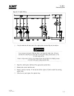
Page 102: ...gout procedures Severe injury can result if the machine is not properly locked out Observe electrical Lockout Tagout procedures before performing maintenance on the system components Ensure all pressure is relieved or blocked from the hydraulic and high pressure circuits before performing maintenance 2 Remove the electrical cable from the failed proximity switch 3 Remove the two socket head screws...

Page 103: ...If the relay or the fuse for the relay fails the state will not change For example if the relay controlling the two pressure solenoid valve fails the machine will not switch between low and high pressure operation Table 8 3 Optical Relays Label Component Function 4K1 Directional Control Valve Solenoid A Switches the direction of the hydraulic flow 4K2 Directional Control Valve Solenoid B Switches ...

Page 104: ...ckout Tagout procedures before performing maintenance on the system components Ensure all pressure is relieved or blocked from the hydraulic and high pressure circuits before performing maintenance 2 Open the control panel and locate the appropriate optical relay 3 Remove the screws and the relay 4 Remove and test the fuse If the fuse has failed replace it and re install the existing optical relay...

Page 105: ...ide of the hydraulic cylinder or the other As the flow is sent to one side hydraulic fluid is returned to the reservoir from the opposite side Figure 9 1 High Pressure Water System Circuit System components include a double ended hydraulic cylinder reciprocating piston assembly high pressure cylinders attached to each end of the hydraulic cylinder two plungers sealing heads and hard seal end caps ...

Page 106: ...tivates the proximity switch at the end of the stroke The hydraulic flow is then sent to the opposite side of the cylinder and the piston reverses direction until it activates the proximity switch at the opposite end of the stroke Figure 9 2 High Pressure Water System The green light on the proximity switch indicates there is power to the switch The red light illuminates when the switch is activat...

Page 107: ...pply of water From the attenuator the high pressure water exits to the cutting head The safety dump valve releases the stored pressure in the intensifier and high pressure delivery lines The high pressure dump valve assembly includes a normally open high pressure water valve and an electrically controlled air valve The normally open pneumatic dump valve is held closed by air pressure When the air ...

Page 108: ...me inactive 1 Turn the machine off and make sure the emergency stop button is depressed 2 Turn the cutting water supply off 3 Disconnect the low pressure water supply lines from intensifier 1 and connect them to intensifier 2 4 Remove the side cover to gain access to the hydraulic hand valves and close the two hydraulic shutoff valves to intensifier 1 5 Close the high pressure water shutoff valve ...

Page 109: ...idual high pressure water system components NOTE System components specifications and some maintenance procedures are determined by the horsepower rating and or plunger diameter The information in this section is organized and presented accordingly Figure 9 4 High Pressure Cylinder Assembly Figure 9 5 Hydraulic Cylinder Assembly ...

Page 110: ...ntensifier and bleeds high pressure water through the dump valve Improper assembly can lead to the premature failure of components Maintenance procedures must be followed carefully components must be properly cleaned prior to assembly and tightened to the correct torque specifications Some high pressure components are not serviceable at the customer level others require precise refinishing KMT Wat...

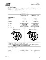
Page 111: ...ft lbs 27 Nm Crossing Pattern 3rd Stage 32 35 ft lbs 43 47 Nm Crossing Pattern 32 35 ft lbs 43 47 Nm Crossing Pattern 4th Stage 32 35 ft lbs 43 47 Nm Clockwise Pattern From Bolt 1 32 35 ft lbs 43 47 Nm Clockwise Pattern From Bolt 1 Socket Wrench Size 3 8 inch 3 8 inch 6 Bolt Crossing Pattern 8 Bolt Crossing Pattern Note Crossing Pattern 1 2 3 4 5 6 or 1 2 3 4 5 6 7 8 Note A maximum torque of 38 ft...

Page 112: ... Discharge Gland Nut 130 ft lbs 176 Nm 200 ft lbs 271 Nm Poppet Retainer Screw s 25 in lbs 2 8 Nm 50 in lbs 5 6 Nm 3 Port Pneumatic Valve HP Adapter 25 ft lbs 34 Nm 1 4 inch Outlet to Drain 25 ft lbs 34 Nm Pneumatic Actuator 5 ft lbs 7 Nm 3 8 inch HP Gland Nut 50 ft lbs 68 Nm 2 Port Pneumatic Valve 3 8 inch HP Gland Nut 50 ft lbs 68 Nm 1 4 inch HP Gland Nut 25 ft lbs 34 Nm Pneumatic Actuator 5 ft ...

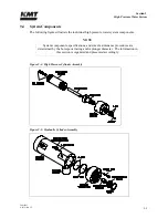
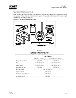
Page 113: ...ols and part numbers are provided in Table 9 2 Figure 9 7 Specialized Maintenance Tools Table 9 2 Specialized Maintenance Tools High Pressure Water System Part Number 7 8 Diameter Plunger 1 1 8 Diameter Plunger Plunger Removal Tool 20477460 20477469 Plug 10079523 3 8 10078772 9 16 Gland Fitting 10078129 3 8 10078608 9 16 Seal Removal Tool 10148674 05146618 End Cap Wrench 80079239 6x 8x Cylinder Wr...

Page 114: ...t on the hard seal end cap 4 When the required maintenance has been completed and the components reassembled connect the low pressure water piping to the inlet water port on the hard seal end cap 5 Apply Pure Goop to the threads on the high pressure gland fitting Before installing the high pressure fitting ensure proper collar position 1 1 2 to 2 1 2 threads should be exposed Install and tighten t...

Page 115: ...nsure all pressure is relieved or blocked from the hydraulic and high pressure circuits before proceeding 2 Disconnect the high and low pressure water piping following the procedure High and Low Pressure Water Piping NOTE Prior to removal verify that the alignment marks on the high pressure cylinder and on the hydraulic cylinder head are aligned If not check the condition of the retaining ring and...

Page 116: ... and that the threads have been sanded and dressed if galling was encountered during removal 2 Verify that the high pressure seal assembly packing follower and cylinder liner are correctly installed Align the cylinder assembly with the plunger and the hydraulic cylinder head using the cradle tool to support the weight Carefully push and lift the assembly into position until the threads are ready t...

Page 117: ...o high pressure soon after the intensifier starts pumping water There is no further need to flush air from the system High Pressure Cylinder Maintenance The plunger seal area in the high pressure cylinder bore should be inspected and cleaned each time the high pressure seal assembly is replaced 1 Clean the sealing area on the inside diameter of the high pressure cylinder and inspect the bore for r...

Page 118: ...serviced The plunger will extend in the selected direction allowing full exposure when the unit is disassembled 1 Turn the machine off and observe the appropriate Lockout Tagout procedures Severe injury can result if the machine is not properly locked out Observe electrical Lockout Tagout procedures before proceeding Ensure all pressure is relieved or blocked from the hydraulic and high pressure c...

Page 119: ...to the internal threads in the HSEC Install the jackbolts ensuring they are slightly less than flush with the inner face of the end cap Make sure the JL M lube is well mixed and not dried up due to age 4 Position the end cap on the high pressure cylinder and fully engage the threads on the end cap with the high pressure cylinder The cone seal on the sealing head should be in contact with the cylin...

Page 120: ...dule Service is recommended every 1 500 hours The discharge check valve can be serviced with the sealing head either installed or removed from the high pressure cylinder 1 Turn the machine off and observe the appropriate Lockout Tagout procedures Severe injury can result if the machine is not properly locked out Observe electrical Lockout Tagout procedures before proceeding Ensure all pressure is ...

Page 121: ...High Pressure Discharge Check Valve 7 Apply a thin film of Pure Goop to the face of the seat opposite the discharge poppet and install the seat into the sealing head If the existing seat is reused install the seat with the new surface facing the poppet 8 Install the poppet pin and the spring with the larger end of the spring facing the poppet and then install the poppet into the gland nut 9 Apply ...

Page 122: ...emove the retainer and the inlet poppet from the sealing head 1 Use a T20 star drive to remove the poppet retainer screws Remove the retainer and the inlet poppet from the sealing head 2 Inspect the sealing head for scratches or wear on the cone ring contact surface and on the inlet poppet valve contact surface If defects are detected the surfaces must be refinished See the procedure Sealing Head ...

Page 123: ...t moves freely and the poppet retainer screws are seated 6 Inspect the assembled unit to ensure the poppet moves freely and the poppet retainer screw is seated Sealing Head Maintenance The sealing head should be inspected for scratches excessive sealing damage or erosion marking on the cone ring contact surface and on the inlet poppet valve contact surface If defects are detected the surfaces must...

Page 124: ...he Maintenance Screen on the control panel The machine will start in recirculation mode the dump valve will open and relieve the high pressure in the system Press the RIGHT or LEFT arrow to extend the plunger on the end to be serviced The plunger will extend in the selected direction allowing full exposure when the unit is disassembled 1 Turn the machine off and observe the appropriate Lockout Tag...

Page 125: ...linder assembly upright in the seal removal tool stand If a tool stand is not available position the cylinder on a platform of wooden blocks with the jackbolts resting on the platform Do not stand the cylinder assembly on the top pan of the machine The assembly is heavy and must be properly supported to prevent it from falling 6 Fill the cylinder with water and slide the seal removal tool or a use...

Page 126: ...cylinder assembly into the hydraulic cylinder head following the procedure High Pressure Cylinder Assembly Installation 14 Reconnect the high and low pressure water piping and turn the low pressure water supply on 9 11 Hydraulic Cartridge Seal and Plunger Removal The following procedure is used to remove the hydraulic cartridge seal and the plunger Prior to removing electrical power or any high or...

Page 127: ...ly installed and secured prior to starting the machine Failure to tighten the two hold down screws on each switch will result in the spray of hydraulic oil 8 Remove the collet from the plunger removal tool and thread the large end of the tool onto the hydraulic cartridge seal and pull the cartridge out over the plunger Figure 9 15 Hydraulic Cartridge Seal Removal 9 With the cartridge removed the p...

Page 128: ...ridge seal will leak Accumulation of debris on the surface of the plunger can be removed by polishing in a radial direction with 600 grit sandpaper However plunger surface flaws usually cannot be repaired on site The plunger can be returned to KMT Waterjet for reconditioning Figure 9 17 Plunger Plunger Installation To install the plunger slide the plunger removal tool over the plunger with the lob...

Page 129: ...ls closest to the open ends first and work toward the center 2 Inspect the seals for unusual wear deformation or cuts Note any unusual buildup of solid material or debris creating possible leak paths 3 Inspect the surface of the cartridge body for scratches deformation signs of metal to metal contact or other unusual wear Carefully examine the surface of the grooves on the inside diameter Note any...

Page 130: ...d tilt or tip enough to allow the retaining ring to move into the groove Continue working the ring into the groove while tilting the retainer flange until the ring is fully seated 10 Install the high pressure cylinder assembly into the hydraulic cylinder head following the procedure High Pressure Cylinder Assembly Installation 11 Connect the high and low pressure water piping and turn the low pres...

Page 131: ...om both ends of the intensifier following the procedure High and Low Pressure Water Piping 3 Remove the high pressure cylinder assembly on each end of the intensifier following the procedure High Pressure Cylinder Assembly Removal Figure 9 20 Hydraulic Piston Removal 4 Remove both of the proximity switches to prevent interference and to allow the hydraulic oil to drain back to the reservoir minimi...

Page 132: ...c leaks 3 Inspect the bottom of the seal grooves for marks scratches and residue buildup Clean and or repair the groove surfaces as required 4 Apply FML 2 grease to the new bearing rings and install the rings 5 The piston seal assembly consists of an inner and an outer seal ring Apply FML 2 grease to both rings Use the smooth dull edged blade to install the inner ring ensuring the ring is not twis...

Page 133: ... the plunger attachment Use the plunger removal tool to ensure the pins retract to release the plunger and close to retain the plunger in a uniform manner Internal Check Valves It is not necessary to service the internal check valves unless a problem is suspected If the check valves or the internal passages in the piston require service plunger button seal and pin servicing is also recommended See...

Page 134: ...fy that the o ring and backup ring are properly positioned in the groove on both hydraulic cylinder heads and that they are sufficiently lubricated with FML 2 grease 6 Position the cylinder heads in the ends of the hydraulic cylinder Apply JL M grease to the threads on the socket head screws Install the screws in each hydraulic cylinder head and tighten following the torque specifications in Table...

Page 135: ...Maintenance The inside diameter surface of the hydraulic cylinder should be inspected for wear grooves and surface finish whenever the hydraulic cylinder heads are removed Excessive grooving is indicative of piston seal wear 9 14 High Pressure Attenuator The high pressure attenuator is not serviceable at the customer level KMT Waterjet Systems tests the seals in the attenuator at pressures exceedi...

Page 136: ...t or both The high pressure dump valve is a safety device designed to instantly release high pressure from the system Proper maintenance is imperative to prevent potential personal injury Figure 9 23 Pneumatic Valve Seal Tools illustrates the special tools recommended for this procedure Figure 9 23 Pneumatic Valve Seal Tools 3 Port Pneumatic Control Dump Valve SL V 30 50 and 60 For reliable operat...

Page 137: ... Ensure all pressure is relieved or blocked from the hydraulic and high pressure circuits before proceeding 1 Turn the air supply off 2 Remove the air supply hose and the electrical connection to the solenoid valve Figure 9 24 3 Port High Pressure Dump Valve 3 Loosen and remove the high pressure gland connections and the drain connection 4 Remove the valve and actuator assembly from the machine ...

Page 138: ...e adapter and valve seat 7 Remove the stem SST backup ring and brass backup ring from the valve body 8 Remove the seal assembly by pushing it with the seal push tool P N 20470413 The assembly must be pushed out through the actuator port in the top of the valve body 9 Discard the stem brass backup ring seal assembly and valve seat 10 Clean and inspect the valve body being careful not to damage or s...

Page 139: ... of the seal must face the actuator See Figure 9 26 Valve Seal Installation 14 Use the seal push tool to push the seal assembly into the bore of the valve body until the seal makes light contact with the seal positioning tool 15 Remove the push tool and the installation tool from the valve body 16 Install the existing SST backup ring and a new brass backup ring on a new stem The vee groove on the ...

Page 140: ...pound to the threads on the 3 8 inch high pressure gland fittings Install the collar and the gland fittings and torque to 50 ft lbs 68 Nm 24 Install the air supply hose and the electrical connection to the solenoid valve Turn the air pressure to the actuator on and test the valve for leaks and proper operation 2 Port Pneumatic Control Dump Valve SL V 100 For reliable operation the valve seat seal ...

Page 141: ...r Unscrew and remove the actuator from the valve body 6 Unscrew the high pressure bushing and remove the bushing adapter cone and valve seat 7 Remove the stem SST backup ring and brass backup ring from the valve body 8 Remove the seal assembly by pushing it with the seal push tool P N 20470413 The assembly must be pushed out through the actuator port in the top of the valve body 9 Discard the stem...

Page 142: ... of the seal wedge ring end faces the actuator The tapered end of the seal must face the actuator See Figure 9 30 Valve Seal Installation 14 Use the seal push tool to push the seal assembly into the bore of the valve body until the seal makes light contact with the positioning tool 15 Remove the push tool and the installation tool from the valve body 16 Install the existing SST backup ring and a n...

Page 143: ...urfaces except the ID of a new valve seat Install the seat into the opposite end of the valve body inserting the small OD first 21 Apply anti seize compound to the threads on the high pressure bushing and on the back side of the adapter cone Position the adapter cone in the bushing install the bushing and torque to 50 ft lbs 68 Nm 22 Replace the 1 4 inch gland nut and collar and torque to 25 ft lb...

Page 144: ... cylinder Do not install the pneumatic cylinder in a vise to remove the cylinder head This may distort the body and seize the piston preventing proper operation 2 Remove the o ring on the cylinder head Apply FML 2 grease to a new o ring and install 3 Remove the two o rings on the piston Apply FML 2 grease to two new o rings and install 4 Install the piston in the pneumatic cylinder Apply anti seiz...

Page 145: ...led hydraulic cartridge seal Replace the cartridge seal If the leak persists check the plunger for linear scratches or scoring Water leaking from the weep hole on the hydraulic cylinder head flange Failed high pressure seal assembly Replace the high pressure seal assembly Damaged plunger Check the plunger for longitudinal scratches or flaws If detected replace the plunger or return to KMT for eval...

Page 146: ...ue on gland nut Tighten the gland nut to the proper torque specification Erosion or scratches on the contact surface of the sealing head or on the gland nut where the seat makes contact Polish the surfaces following the procedure Sealing Head Maintenance Water leaking from the weep hole in the gland nut High pressure piping gland nut is not tight and is not sealing properly Tighten the gland nut t...

Page 147: ...for scratches or grooves on the cone seal surface If detected polish to remove following the procedure High Pressure Cylinder Maintenance External crack in sealing head Replace the sealing head Damaged sealing head Check for scratches or grooves on the cone seal surface of the sealing head If detected polish the surface following the procedure Sealing Head Maintenance Improper torque on jackbolts ...

Page 148: ...Hydraulic pressure but no high pressure water pressure 10 Erratic fluctuations in the operating pressure or inability to reach or maintain set pressure 11 No hydraulic oil pressure 12 Pump shaft will not turn 13 Pump will not start 14 Console display and lights do not illuminate 15 Pump quits running 16 No control power 17 Red light on operator s console is flashing 18 Abnormal fluctuations in hig...

Page 149: ... 2 Booster pump pressure drop is greater than 30 psi 2 bar during stroke condition Inlet water pressure or flow is low Filter element is dirty and needs to be replaced Booster pump is starting to fail If the pressure consistently drops below 60 psi 4 bar the pump will need to be replaced 3 Outlet booster pump pressure is falling below 60 psi 4 bar Inlet water pressure is low Filter element is dirt...

Page 150: ... Air cooler temperature switch is not operating properly Replace the switch No power to cooler fan motor Check power supply to fan motor Restricted air flow to cooler Ambient temperature is greater than 100º F Restricted oil flow to from or inside the oil cooler 7 Low oil level resulting in shutdown Check the level gauge Check for hydraulic leaks Check the level switch 8 Restricted or no cooling f...

Page 151: ...here are inputs from the proximity switches but no outputs contact the KMT Customer Service Department for a logic review and verification of PLC failure 10 Erratic fluctuations in the operating pressure or inability to reach or maintain set pressure The screen in the proportional pressure valve is blocked with debris Remove the valve and clean the screen following the maintenance procedure in Sec...

Page 152: ...relay A protection fault has been activated Check the display panel for fault messages Motor overload relay has been tripped Identify the source of the overload and remedy the problem Reset the overload relay Inlet water valve is turned off Press the reset button on the Run Screen to reset the water valve 14 Console display and lights do not illuminate Emergency stop button is depressed Pull the e...

Page 153: ...he 4K0 relay Motor overload relay has been tripped Identify the source of the overload and remedy the problem Reset the overload relay 16 No control power Circuit breaker has been tripped Check the input and output of all circuit breakers Power supply fault Check the input and output voltages at the power supply Emergency stop button is depressed Pull the e stop button out Check all remote e stop ...

Page 154: ...Large worn or damaged orifice Make sure the orifice does not exceed the capacity of the pump Make sure the orifice is in good working condition Verify that the jewel is installed in the orifice mount Check valve leakage Inspect the discharge check valves in the sealing heads Inspect the inlet check valves in the sealing heads Seal leakage Inspect the high pressure seal on the plunger Inspect the s...

Page 155: ...ace if necessary Damaged high pressure cylinder Check the high pressure cylinder for cracks 20 Low cutting water supply pressure Restricted water supply Check cutting water supply flow and pressure Clogged water filter Check the condition of the low pressure water filter and replace the filter element if necessary Trapped air Bleed the air from the cutting water plumbing 21 Low cutting water press...

Page 156: ...ed plunger Check the plunger for longitudinal scratches or flaws If detected replace the plunger or return to KMT Waterjet for evaluation and rework Seal material buildup on plunger Polish the plunger surface following the procedure Plunger Maintenance detailed in Section 9 High Pressure Water System Damaged high pressure cylinder Check for scratches grooves or material buildup on the inside diame...

Page 157: ...ealing head body can become extremely hot Erosion or scratches on the contact surface of the sealing head or on the gland nut where the seat makes contact Polish the surfaces following the procedure Sealing Head Maintenance detailed in Section 9 High Pressure Water System 25 Water leaking from the weep hole in the sealing head gland nut High pressure piping gland nut is not tight and is not sealin...

Page 158: ...following the procedure High Pressure Cylinder Maintenance detailed in Section 9 High Pressure Water System Replace the high pressure cylinder External crack in sealing head Replace the sealing head Damaged sealing head Check for scratches or grooves on the cone seal surface of the sealing head If detected polish the surface following the procedure Sealing Head Maintenance detailed in Section 9 Hi...

Page 159: ...lation contactor for proper closure Check presence of line power LED flashing one time overload Reset overload LED flashing two times over temperature Allow time for unit to cool LED flashing four times phase loss open load Check line and load connections to the softstarter contactors and motor Confirm that 3 phase is present LED flashing five times phase imbalance Check the line current present i...

Page 160: ...sence of line power LED flashing one time overload Reset overload LED flashing two times over temperature Allow time for unit to cool LED flashing four times phase loss open load Check line and load connections to the softstarter contactors and motor Confirm that 3 phase is present LED flashing five times phase imbalance Check the line current present in each phase The unit will trip if imbalance ...

Page 161: ...w SL V 30 30 22 SL V 50 50 37 SL V 60 60 45 SL V 100 100 75 11 2 Installation Specifications Environment Installation location Indoors Air borne dust contaminants Minimal Ambient temperature Minimum storage 36 F 2 C Minimum operating 40 F 5 C Maximum operating 104 F 40 C Maximum relative humidity at maximum operating temperature 95 Note When the relative humidity is above 50 the oil in the reservo...

Page 162: ...360 kg 60 HP 3 500 lbs 1 588 kg 100 HP 4 600 lbs 2 087 kg Service Connections Connection Height A Drain 1 2 NPT 7 50 191 mm B Cutting Water In 1 2 NPT 10 50 267 mm C Cooling Water In oil to water models 1 2 NPT 13 50 343 mm Hydraulic Oil In air to water models 3 4 JIC D Cooling Water Out oil to water models 1 2 NPT 16 50 419 mm Hydraulic Oil Out air to water models 3 4 JIC E Plant Air In 1 4 NPT 3...

Page 163: ... 1 94 F 60 C 0 01 2 1 40 F 40 C 0 1 3 5 4 F 20 C 1 4 15 38 F 3 C 5 5 40 45 F 7 C 25 6 50 F 10 C 11 3 Water Specifications Cutting Water Supply Low Pressure Water System 30 HP 50 HP 60 HP 100 HP Maximum consumption gpm L min 2 5 9 5 4 0 15 1 4 5 17 0 8 0 30 0 Minimum inlet water pressure 35 psi 2 4 bar flowing Maximum inlet water pressure 80 psi 5 5 bar Maximum outlet water pressure 120 psi 8 3 bar...

Page 164: ... water pressure oil to water models 35 psi 2 4 bar Maximum inlet cooling water pressure oil to water models 100 psi 6 9 bar Oil filtration rating Beta filtration rating β10 100 Fluid cleanliness rating ISO fluid cleanliness rating 17 14 Nominal recirculation pressure 30 psi 2 bar Recommended oil type General service Mobil DTE 26 Grade 68 Conoco Hydroclear TM multi purpose R O Food service Fuchs Ge...

Page 165: ...ially calcium silica and chlorides will affect high pressure component life Table 11 3 Water Quality Standards Constituent mg l or ppm Minimum Requirement Better Best Alkalinity 50 25 10 Calcium 25 5 0 5 Chloride 100 15 1 Free Chlorine 1 1 0 05 Iron 0 2 0 1 0 01 Magnesium as Mg 0 5 0 1 0 1 Manganese as Mn 0 1 0 1 0 1 Nitrate 25 25 10 Silica 15 10 1 Sodium 50 10 1 Sulfate 25 25 1 TDS 200 100 35 Tot...

Page 166: ...dissolved makes water hard contributes to the formation of scale Manganese as Mn Mn Discolors water or precipitation source of scale and erosion Nitrate NO3 Adds to solid content effect is not generally significant industrially Silica SiO2 Causes scale Sodium Na Found naturally introduced to water in the ion exchange water softening process Sulfate SO4 Adds to solid content combines with calcium t...

Page 167: ...Circuit Breaker Amps 208 3 60 30 80 125 230 3 60 30 76 100 400 3 50 30 43 60 415 3 50 30 43 60 460 3 60 30 38 50 575 3 60 30 32 40 200 3 50 60 50 132 175 200 3 50 60 50 132 175 208 3 50 60 50 128 175 230 3 60 50 116 150 380 3 50 50 69 100 400 3 50 50 66 100 415 3 50 50 64 100 460 3 60 50 58 80 575 3 60 50 52 70 230 3 60 60 140 175 380 3 60 60 86 125 460 3 60 60 70 90 200 3 50 60 100 248 350 200 20...

Page 168: ... 60 HP 100 HP Plunger diameter inches mm 0 875 22 0 875 22 0 875 22 1 125 29 Piston diameter inches mm 4 03 102 4 4 03 102 4 4 03 102 4 5 50 139 7 Intensification ratio 20 1 20 1 20 1 23 1 Maximum flow rate 55 000 psi 3 792 bar gpm L min 0 60 2 27 1 00 3 79 1 12 4 24 2 00 7 57 60 000 psi 4 137 bar gpm L min 0 52 1 97 0 90 3 41 1 02 3 86 1 88 7 12 Minimum outlet pressure 5 800 psi 400 bar 5 800 psi...

Page 169: ...Table 11 6 Horsepower Requirements Orifice Size inches mm 45 000 psi 3 103 bar 50 000 psi 3 447 bar 55 000 psi 3 792 bar 60 000 psi 4 137 bar 0 003 0 076 1 7 2 0 2 3 2 6 0 004 0 102 3 0 3 5 4 0 4 6 0 005 0 127 4 6 5 4 6 2 7 1 0 006 0 152 6 7 7 8 9 0 10 2 0 007 0 178 9 1 10 6 12 2 13 9 0 008 0 203 11 8 13 9 16 0 18 2 0 009 0 229 15 0 17 5 20 2 23 0 0 010 0 254 18 5 21 6 25 0 28 5 0 011 0 279 22 4 2...

Page 170: ...021 0 533 81 5 95 4 110 1 125 5 0 022 0 559 89 4 104 8 120 9 137 7 0 023 0 584 97 8 114 5 132 1 150 5 The horsepower requirements for operating multiple orifices are determined by adding the requirements in Table 11 6 for each orifice Examples are shown below Orifice Size inches mm Number of Orifices Operating Pressure Calculation Total Horsepower 0 009 0 229 3 55 000 3 x 20 2 60 6 0 015 0 381 0 0...

Page 171: ... potential hazards to equipment and personnel Torque Specifications 7 8 inch 22 mm Diameter Plunger 1 1 8 inch 29 mm Diameter Plunger Hard Seal End Cap Jackbolts 6 7 16 each 8 7 16 each 1st Stage Hand Tight Hand Tight 2nd Stage 20 ft lbs 27 Nm Crossing Pattern 20 ft lbs 27 Nm Crossing Pattern 3rd Stage 32 35 ft lbs 43 47 Nm Crossing Pattern 32 35 ft lbs 43 47 Nm Crossing Pattern 4th Stage 32 35 ft...

Page 172: ...4 3 8 each Torque 60 65 ft lbs 80 88 Nm 35 40 ft lbs 47 54 Nm Hex Key M8 5 16 inch Sealing Head Discharge Gland Nut 130 ft lbs 176 Nm 200 ft lbs 271 Nm Poppet Retainer Screw s 25 in lbs 2 8 Nm 50 in lbs 5 6 Nm 3 Port Pneumatic Valve HP Adapter 25 ft lbs 34 Nm 1 4 inch Outlet to Drain 25 ft lbs 34 Nm Pneumatic Actuator 5 ft lbs 7 Nm 3 8 inch HP Gland Nut 50 ft lbs 68 Nm 2 Port Pneumatic Valve 3 8 i...

Page 173: ...ying numbers in the accompanying figures Use the following information to contact the Customer Service Department at KMT Waterjet Systems USA Europe Customer Service Department KMT Waterjet Systems PO Box 231 635 West 12th Street Baxter Springs KS 66713 0231 USA Spare Parts Manager KMT Waterjet Systems GmbH Wasserstrahl Schneidetechnik Auf der Laukert 11 D 61231 Bad Nauheim Germany Phone Fax Email...

Page 174: ...cal Assembly 49830938 12 33 12 5 Pneumatic Valve Actuator Assembly 10184760 12 10 12 17 Controls Subassembly 80077845 12 35 12 6 Hydraulic Piston Assembly 05146576 12 12 12 18 Control Panel Configuration 80074156 12 38 12 7 High Pressure Piping 2L Attenuator 20429831 12 14 12 19 Control Panel Configuration 20493065 12 40 12 8 Low Pressure Water Filter Assembly 80087976 12 16 12 20 Proportional Pre...

Page 175: ...4 Autoline Sapphire Orifice 12 67 12 26 Focusing Tubes 12 52 12 35 Autoline Diamond Orifice 12 67 12 27 Standard Sapphire Orifice 12 54 12 36 Pneumatic Control Valve NC 10138824 12 68 12 28 Standard Diamond Orifice 12 54 12 37 Pneumatic Cylinder Assembly NC 10177855 12 69 12 29 High Pressure Filter Assemblies 12 55 12 38 Pneumatic Control Valve NO 10184760 12 70 12 30 High Pressure Swivel Joints 1...

Page 176: ...dant Kit Optional 1 4 20461179 Decal Package 100 Horsepower Single 1 5 05128087 Startup Tag 1 6 80079668 Bulkhead Pipe Assembly 1 7 05141569 Frame Assembly 1 8 05104153 Reservoir Assembly 1 9 80074768 Cover Assembly 1 10 49835846 Hydraulic Power Package 1 11 05142351 Hydraulic Hose Connections 1 12 20461257 Striping Red 45 0 13 10097657 Button Head Screw 1 4 20 x 3 4 4 14 95391322 Flat Washer 25 4...

Page 177: ...Section 12 Parts List 20413146 8 2012 Rev 12 12 5 Figure 12 1 SL V 100 Horsepower Intensifier Unit ...

Page 178: ...C DC 2 5 05149711 HP Seal Assembly 2 20 95119012 Socket Head Screw 1 4 x 20 x 1 4 7 49838220 HP Cylinder Nut HSEC 2 21 05146576 Piston Assembly 1 8 05146584 Hydraulic Cartridge Seal Assembly 2 23 05144522 Topworks Support 2 9 05145099 Bushing Retainer Flange 2 25 05041058 Socket Head Screw 3 8 16 x 2 1 4 8 11 72110945 Liner HP Cylinder 2 26 95688743 Lock Washer 38 8 12 10074920 O Ring 1 75 x 94 x ...

Page 179: ...Section 12 Parts List 20413146 8 2012 Rev 12 12 7 Figure 12 2 Intensifier Assembly ...

Page 180: ...scription Quantity 1 05144530 Seal Bushing 1 5 10168912 O Ring 1 25 x 1 38 x 06 1 2 10142032 Packing Ring 1 38 x 1 13 x 25 2 6 05116124 O Ring 1 50 x 1 63 x 06 1 3 10145431 O Ring 1 44 x 1 63 x 09 1 7 05116132 U Cup Seal 1 13 x 1 38 x 13 1 4 05116140 Backup Ring 1 44 x 1 63 1 80085061 Rebuild Kit Includes Items 2 7 Figure 12 3 Hydraulic Cartridge Seal ...

Page 181: ...ing Head Body 1 5 05116603 Discharge Poppet Valve 1 2 72112002 Inlet Poppet Valve 1 6 72106104 Button Head Screw 8 32 x 3 8 2 3 05116595 Gland Nut 1 7 05147863 Compression Spring 1 4 05116579 Seat 1 8 72110953 Poppet Retainer 1 9 05119839 Poppet Pin 1 05133335 Rebuild Kit Includes Items 4 5 7 and 9 72125203 Rebuild Kit Includes Items 2 4 5 6 7 and 9 Figure 12 4 Sealing Head Assembly ...

Page 182: ...9181 Valve Body 1 10189553 Actuator Assembly Normally Open 2 10178697 Valve Seat 1 6 BV401184 Pneumatic Cylinder 1 3 20435636 Valve Stem 1 7 BV601184 Cylinder Head 1 4 10188233 Backup Ring Brass 1 8 BV501184 Piston 1 5 20428052 Seal Assembly 1 9 10187250 Backup Ring SST 1 10 10074714 O Ring 2 44 x 2 63 x 09 1 11 10074565 O Ring 2 25 x 2 38 x 06 2 05116017 Rebuild Kit Includes Items 2 3 4 5 10 and ...

Page 183: ...Section 12 Parts List 20413146 8 2012 Rev 12 12 11 Figure 12 5 Pneumatic Valve Actuator Assembly Normally Open ...

Page 184: ...05074380 Plunger Retainer Pin Clevis 12 3 05049887 Set Screw Socket 3 8 16 x 3 8 2 4 10148757 Check Valve 2 5 49877509 Adhesive Thread Locker 6 05130216 Flat Snap Ring 032 x 375 x 2 20 2 7 05146568 Backup Ring 1 50 x 1 75 x 125 2 8 10074821 O Ring 1 50 x 1 75 x 13 2 9 05120118 Seal Assembly 1 10 05120100 Bearing Ring 2 80085079 Rebuild Kit Includes Items 4 6 7 8 9 and 10 ...

Page 185: ...Section 12 Parts List 20413146 8 2012 Rev 12 12 13 Figure 12 6 Hydraulic Piston Assembly ...

Page 186: ...be 56 x 4 97 1 24 05112552 HP Tube 25 x 34 0 1 8 10078525 Elbow HP 56 x 56 7 25 10079705 Coupling HP Bulkhead 56 x 56 1 9 49895642 HP Tube 56 x 9 25 1 26 95413696 Lock Washer 50 4 10 10069326 HP Tube 56 x 4 0 5 27 95383790 Socket Head Screw 1 2 13 x 1 4 11 05145271 HP Tube 56 x 55 19 1 28 10079119 HP Collar 56 3 12 05145297 HP Tube 56 x 4 18 1 29 20424324 Attenuator Housing 1 13 20429847 HP Tube 5...

Page 187: ...Section 12 Parts List 20413146 8 2012 Rev 12 12 15 Figure 12 7 High Pressure Piping ...

Page 188: ...Pipe Nipple 75 x 4 0 2 12 49833882 Adapter Hose ORB 50 x 50 3 5 10119253 Elbow Pipe 50 x 50 1 13 95838314 Lock Washer 25 4 6 20413848 Low Pressure Manifold Outlet 1 14 49834716 Filter Element 10 Micron 1 7 49833924 Low Pressure Manifold Left 1 15 95391322 Flat Washer 25 4 9 49835804 Adapter Hose Pipe 50 x 50 2 16 10083384 U Bolt 75 2 10 72118339 Filter Housing Assembly 1 Ref 1 05073630 Mounting Br...

Page 189: ...Section 12 Parts List 20413146 8 2012 Rev 12 12 17 Figure 12 8 Low Pressure Water Filter Assembly ...

Page 190: ... 17 72111838 Manifold Pilot 1 5 49836778 Water Pump Vane 1 18 10069581 Lock Washer 25 2 6 49835754 Pressure Gauge 0 5000 psi 1 19 10144376 Socket Head Screw 1 4 20 x 1 1 4 2 7 05103429 Shaft Spline 1 20 72111986 Relief Valve 1 8 80081733 Relief Valve 205 Bar 1 21 10187060 Relief Valve 1 9 80079684 Adapter FSOR ORB 1 0 x 75 2 22 05055017 Plug ORB 13 2 10 05103395 Shaft Coupling 1 23 10185585 Soleno...

Page 191: ...Section 12 Parts List 20413146 8 2012 Rev 12 12 19 Figure 12 9 Hydraulic Power Package ...

Page 192: ... 10 x 2 1 2 4 19 05085758 Adapter ORB JIC 38 x 25 1 6 80076656 Flange Motor Pump Adapter 1 20 10091163 Adapter JIC ORB 75 x 75 1 7 05103239 Piston Pump 1 21 10118057 Plug ORB 75 1 8 10192961 Socket Head Screw M12 x 1 75 x 30 mm 2 22 10099760 Adapter JIC ORB 1 25 x 1 25 1 9 10069763 Flat Washer 50 2 23 05139639 Bushing ORB M14 x 25 1 10 72112043 Manifold Assembly 1 24 80076664 Coupling Pump Shaft 1...

Page 193: ...Section 12 Parts List 20413146 8 2012 Rev 12 12 21 Figure 12 10 Motor Pump Assembly ...

Page 194: ...2 11 Hydraulic Manifold Assembly 72112043 Item Part Number Description Quantity 1 72112035 Hydraulic Manifold 1 2 10187417 O Ring 1 50 x 1 69 x 09 1 3 05071055 Plug ORB 75 3 4 05103189 Check Valve 1 5 49876089 Adapter JIC ORB 25 x 25 1 6 49889769 Plug ORB 25 1 ...

Page 195: ...Section 12 Parts List 20413146 8 2012 Rev 12 12 23 Figure 12 11 Hydraulic Manifold Assembly ...

Page 196: ...e Assembly 1 25 x 26 50 1 9 05051214 Hydraulic Hose Assembly 25 x 39 0 1 3 05106976 Hydraulic Hose Assembly 1 25 x 24 50 1 10 80079809 Adapter FSOR ORB 1 0 x 75 2 4 20419045 Hose Clamp 3 0 4 11 80079536 Hydraulic Hose Assembly 1 0 x 36 0 2 5 10079754 Radiator Hose 2 50 10 5 12 80085889 Hydraulic Hose Assembly 25 x 20 0 1 6 49872245 Split Flange 2 50 1 13 05061163 Hydraulic Hose Assembly 75 x 31 0 ...

Page 197: ...Section 12 Parts List 20413146 8 2012 Rev 12 12 25 Figure 12 12 Hydraulic Hose Connections ...

Page 198: ...Temperature Gauge 1 19 05079371 Adapter BSPP JIC 75 x 75 1 6 05103809 Filter Head 1 20 05006291 Diffuser Return Line 1 7 05104187 Filter Element 1 21 10142644 Adapter JIC ORB 25 x 25 2 8 10151470 Adapter ORB JIC 1 0 x 75 1 22 10080901 Ball Valve 1 9 05069976 Cap JIC 75 1 23 10091163 Adapter JIC ORB 75 x 75 2 10 20455107 Tee JIC ORB 75 x 1 0 1 24 95033619 Plug Pipe 50 1 11 05145941 Heat Exchanger W...

Page 199: ...Section 12 Parts List 20413146 8 2012 Rev 12 12 27 Figure 12 13 Reservoir Assembly ...

Page 200: ...19 Hex Head Screw 3 8 16 x 1 16 8 49888035 Solenoid Valve 24V DC 1 27 95750394 Lock Washer 38 16 9 10070092 Jam Nut 1 14 5 28 49833882 Adapter Hose ORB 50 x 50 1 10 10073823 Tee 50 x 50 1 29 10077030 Adapter Tube Pipe 25 x 13 2 11 20413789 Manifold LP Water Inlet 1 30 10079903 Tube Clear 25 36 0 12 80087976 LP Water Filter Assembly 1 31 49834310 Adapter Pipe Tube 50 x 50 1 13 49834328 Adapter Pipe...

Page 201: ...9 Table 12 14 Bulkhead Pipe Assembly 80079668 Item Part Number Description Quantity Item Part Number Description Quantity 39 49831480 Grommet Rubber 3 0 7 41 49868813 Temperature Sensor 1 40 05142062 Pressure Switch 60 psi 1 42 20453730 Check Valve 1 ...

Page 202: ...Section 12 Parts List 20413146 8 2012 Rev 12 12 30 Figure 12 14 Bulkhead Pipe Assembly ...

Page 203: ......

Page 204: ...34690 Cover Right End 2 7 49837511 Mounting Bracket 4 8 49837529 Mounting Bracket 4 9 49837503 Spring Gas 4 10 49837743 Button Head Screw 3 8 16 x 1 0 32 11 05091988 Flange Nut 3 8 16 32 12 95897948 Button Head Screw 10 24 x 1 2 24 13 49832181 Flange Nut 10 24 24 14 80074719 Gasket Not Shown 1 15 95670972 Lock Washer 38 6 16 05091954 Button Head Screw 3 8 16 x 1 00 6 17 80076748 Cable Lanyard 18 7...

Page 205: ...Section 12 Parts List 20413146 8 2012 Rev 12 12 32 Figure 12 15 Cover Assembly ...

Page 206: ... 10125912 Cable Tie 87 5 4 10098788 Flexible Conduit 2 0 42 0 14 Starter Control Panel Configuration 1 5 10114932 Flexible Conduit Connector 2 0 1 15 80078140 Conduit Reducing Bushing 2 50 x 2 0 1 6 05147251 Conduit Bushing 2 0 x 2 0 1 16 05107347 Conduit Locknut 2 50 1 7 10069763 Flat Washer 50 4 17 05112545 Conduit Locknut 2 50 1 8 05014972 Weld Cable 4 504 0 18 10098937 Gasket Assembly Flexible...

Page 207: ...Section 12 Parts List 20413146 8 2012 Rev 12 12 34 Figure 12 16 Electrical Assembly ...

Page 208: ...y Stop Switch 1 25 20497660 Lamp Block 2 8 20419143 Contact Block 3 26 05140629 Legend Plate Holder Black 1 9 05049473 Legend Plate 1 27 05140579 Mounting Adapter Contact Block 1 10 05032438 Terminal Block 22 14 28 28 20414500 Subplate Electrical Enclosure 1 11 05032362 End Anchor Terminal Block 4 29 10156859 I O Rack 4 Slot 1 12 05032370 End Barrier 1 30 10146363 Single Point Output Module 4 13 0...

Page 209: ...M 2 Green Yellow 36 0 54 05114889 Legend Plate Remote Control On Off 1 41 10094712 Ring Terminal 14 10 1 4 3 55 05117601 End Barrier 3 Level Terminal Block 1 42 95416335 Hex Nut 1 4 20 4 59 05115704 Terminal Block 16 6 1 43 10149086 Pilot Light Red 1 60 05144308 Programmable Controller 1 44 Not used on this assembly 61 49874233 Hole Seal 1 50 Conduit Hole 2 45 10102242 Spiral Wrap 38 12 0 62 49874...

Page 210: ...Section 12 Parts List 20413146 8 2012 Rev 12 12 37 Figure 12 17 Controls Subassembly ...

Page 211: ......

Page 212: ...877 Contactor Non Reversing 72A 230V AC 2 24 49833429 Timing Relay 1 5 30 Second 1 8 10157667 Pan Head Screw 10 32 x 3 4 8 25 10185395 Connector Crimp Ferrule 16 8 9 10103034 DIN Mounting Rail 29 0 26 10176410 Wire 16 Blue 48 0 10 05111448 Overload Relay 26 85A Class 10 1 27 10170165 Wire 16 1 MM 2 Green Yellow 48 0 11 05111471 Interlock Contactor 1 28 49836562 Control Transformer 200V A 1 12 8007...

Page 213: ...Section 12 Parts List 20413146 8 2012 Rev 12 12 39 Figure 12 18 Control Panel Configuration Wye Delta ...

Page 214: ...Wire 14 Black 90 0 6 80080385 Terminal Breaker 2 22 05019617 Connector Crimp Ferrule 14 12 7 20452908 Welding Cable 1 72 0 23 05140686 Circuit Breaker 600V 1 8 05145545 Connector Crimp Ferrule 1 6 24 05032362 End Anchor 5 9 20488290 Controller Softstart 1 25 05140876 Power Supply 24VDC 1 10 10157667 Pan Head Screw 10 32 x 3 4 8 26 Controls Subassembly 1 11 10103034 DIN Mounting Rail 29 0 27 498365...

Page 215: ...Section 12 Parts List 20413146 8 2012 Rev 12 12 41 Figure 12 19 Control Panel Configuration Softstart ...

Page 216: ...oportional Pressure Control 80075732 Item Part Number Description Quantity 1 80071087 Hydraulic Solenoid Valve 24V Cartridge 1 2 49867104 Cable 18 4 Conductor 96 0 3 10067205 Cable Connector 50 1 4 10176410 Wire 16 Blue 100 0 5 10185395 Connector Crimp Ferrule 16 10 ...

Page 217: ...Section 12 Parts List 20413146 8 2012 Rev 12 12 43 Figure 12 20 Proportional Pressure Control ...

Page 218: ...9465 Tee HP 56 1 3 20412627 HP Tube 56 x 11 50 1 4 10079580 Bushing HP 56 x 25 1 5 05071782 HP Tube Bent 25 1 6 49838478 Pressure Transducer 0 75 000 psi 1 7 10067205 Cable Connector 50 1 8 10176410 Wire 16 Blue 100 0 9 10185395 Connector Crimp Ferrule 16 10 10 10078459 HP Gland 25 1 11 10078426 HP Collar 25 1 12 05086905 Flexible Conduit 63 12 0 13 05131347 Ferrule 50 2 ...

Page 219: ...Section 12 Parts List 20413146 8 2012 Rev 12 12 45 Figure 12 21 High Pressure Transducer ...

Page 220: ...078608 HP Gland 56 2 6 80079551 Ball Valve 2 Way 4 21 10079119 HP Collar 56 2 7 80079692 Adapter FSOR ORB 1 0 x 1 0 4 22 05086905 Conduit 63 60 0 8 20417552 Connector Plug W Bead 2 23 05131347 Ferrule 50 Hose 2 9 10067205 Connector Cable 50 2 24 95413696 Lock Washer 50 4 10 10083012 Lock Nut 50 2 25 95383790 Socket Head Screw 1 2 13 x 1 4 11 10082857 Gasket Assembly 2 27 20417180 SST Tubing 2 12 0...

Page 221: ...Section 12 Parts List 20413146 8 2012 Rev 12 12 47 Figure 12 22 Redundant Kit ...

Page 222: ...y 38 Hand Coning Tool Assembly 05108840 Hand Coning Tool Assembly 56 05109897 Power Coning Tool Assembly 25 05109889 Power Coning Tool Assembly 38 05109871 Power Coning Tool Assembly 56 1 05108808 Blade 25 05108824 Blade 38 05108816 Blade 56 2 05108972 Collet 25 05108964 Collet 38 20439964 Collet 56 3 05109814 Retainer 25 Power Coning Tool Assembly 05109822 Retainer 38 05109830 Retainer 56 0512047...

Page 223: ...embly 05108881 Hand Threading Tool Assembly 56 05122742 Power Threading Tool Assembly 25 05120258 Power Threading Tool Assembly 38 05122759 Power Threading Tool Assembly 56 1 05108899 1 4 20 Threading Die 05108915 3 8 16 Threading Die 10078301 9 16 18 Threading Die 2 05108741 Retainer 25 05108758 Retainer 38 Power Threading Tool Assembly 05108766 Retainer 56 05108782 Tube Vise 25 05108790 Tube Vis...

Page 224: ... Tools and Lubricants 20477469 Plunger Removal Tool 1 13 Plunger Maintenance Tools 2 20484961 Vee Block Cradle 3 05066139 Cylinder Wrench 4 80079239 End Cap Wrench HSEC 6x 8x 5 80078330 HP Seal Removal Tool Stand 6 10079523 HP Plug 38 10078772 HP Plug 56 7 10078129 HP Gland 38 10078608 HP Gland 56 8 10148674 HP Seal Installation Tool 88 Plunger 05146618 HP Seal Installation Tool 1 13 Plunger ...

Page 225: ...nstallation Tool 2 05067350 Seal Positioning Tool NO NC Valves 2 Port Dump Valve 3 49833114 Seal Positioning Tool Quick Release Valve 3 Port Dump Valve 4 20470413 Seal Push Tool Lubricants 10084440 Pure Goop Thread Lubricant 1 0 oz 10087385 FML 2 Grease 14 5 oz 49832199 JL M Thread Lubricant 16 oz 80082191 JL M Thread Lubricant 15 ML 20487868 Threadlocker Adhesive 20494983 Threadlocker Primer 1018...

Page 226: ...2 mm x 4 0 101 6 mm 20452161 R 100 0 030 0 762 mm x 6 0 152 4 mm 80075252 R 100 0 036 0 914 mm x 3 13 79 4 mm 49833593 R 100 0 039 0 991 mm x 3 13 79 4 mm 49835390 R 100 0 040 1 016 mm x 3 13 79 4 mm 20432695 R 100 0 043 1 092 mm x 2 0 50 8 mm 10126928 R 100 0 043 1 092 mm x 3 13 79 4 mm 20452135 R 100 0 043 1 092 mm x 4 0 101 6 mm 20452153 R 100 0 043 1 092 mm x 6 0 152 4 mm 10186799 R 100 0 050 ...

Page 227: ... 021 0 533 mm x 2 00 50 8 mm R 500 Focusing Tubes 05105366 R 500 0 043 1 092 mm x 2 75 69 9 mm 05097944 R 500 0 030 0 762 mm x 3 13 79 4 mm 05116652 R 500 0 036 0 914 mm x 3 13 79 4 mm 05097936 R 500 0 043 1 092 mm x 3 13 79 4 mm 05130919 R 500 0 063 1 600 mm x 3 13 79 4 mm 05130927 R 500 0 093 2 632 mm x 3 13 79 4 mm ...

Page 228: ...0006 0 006 0 152 mm A2260014 0 014 0 356 mm A2260024 0 024 0 610 mm A2260007 0 007 0 178 mm A2260015 0 015 0 381 mm A2260028 0 028 0 711 mm A2260008 0 008 0 203 mm A2260016 0 016 0 406 mm A2260032 0 032 0 813 mm Table 12 28 Standard Diamond Orifice Part Number Description Part Number Description Part Number Description 49888852 0 003 0 076 mm 49888910 0 009 0 229 mm 49888969 0 016 0 406 mm Figure ...

Page 229: ...114129 Filter Body 1 HP Inline Water Filter 25 2 05114152 Retainer Filter Element 1 3 05110531 Filter Element 1 4 05114145 Adapter Gland 1 5 10078426 HP Collar 2 6 10078459 HP Gland 2 CJ200988 Inline Water Filter 38 HP Inline Water Filter 38 1 10078715 HP Collar 2 2 10078129 HP Gland 2 3 CJ300988 Filter Body 1 4 CJ400988 Adapter Gland 1 5 SKJA266 Filter Element 1 6 SKJA286 Retainer Filter Element ...

Page 230: ...es Item Part Number Description Quantity BF103473 Inline Water Filter 56 HP Inline Water Filter 56 1 AF413972 HP Gland Outlet 1 2 AF303473 Seal Head Outlet 1 3 AF503473 Filter Element 1 4 BF203473 Filter Body 1 5 AF913972 HP Gland Inlet 1 6 10074599 O Ring 38 x 50 x 06 1 7 AF403473 Seal Head Inlet 1 ...

Page 231: ...12 30 High Pressure Swivel Joints 1 10084713 Thrust Needle Bearing 1 HP Swivel Joint Straight M F Connection 25 2 10094647 Thrust Washer 2 3 10103505 Setscrew 6 32 x 1 8 1 4 CJ311388 Swivel Body 1 5 CJ401288 Swivel Bushing 1 6 CJ501288 Spindle 25 1 7 BJ701288 Cap Assembly 1 8 BJ201388 Seal Assembly 1 BJ701288 Cap Assembly 1 CJ801288 Cap 25 38 M F 1 2 10144442 Swivel Bushing 1 ...

Page 232: ... CJ218088 HP Swivel Joint Straight 25 F F HP Swivel Joint Straight F F Connection 25 1 10084713 Thrust Needle Bearing 1 2 10094647 Thrust Washer 2 3 10103505 Setscrew 6 32 x 1 8 1 4 10154680 Clamp Collar 1 5 CJ318088 Spindle 56 1 6 CJ418088 Cap 25 1 7 CJ311388 Swivel Body 1 8 CJ401288 Swivel Bushing 1 9 BJ201388 Seal Assembly 1 ...

Page 233: ...Joint Straight 38 M F HP Swivel Joint Straight M F Connection 38 1 10084713 Thrust Needle Bearing 1 2 10094647 Thrust Washer 2 3 10103505 Setscrew 6 32 x 1 8 1 4 10134716 Swivel Body 1 5 CJ401288 Swivel Bushing 1 6 49899602 Spindle 38 1 7 BJ701288 Cap Assembly 1 8 BJ201388 Seal Assembly 1 9 10078913 HP Gland Anti Vibration 2 10 10078715 HP Collar 2 ...

Page 234: ...iption Quantity CJ201288 HP Swivel Joint 90D 25 M F HP Swivel Joint 90D M F Connection 25 1 10084713 Thrust Needle Bearing 1 2 10094647 Thrust Washer 2 3 10103505 Setscrew 6 32 x 1 8 1 4 DJ301288 Swivel Body 1 5 CJ401288 Swivel Bushing 1 6 CJ501288 Spindle 25 1 7 BJ701288 Cap Assembly 1 8 BJ201388 Seal Assembly 1 ...

Page 235: ...ntity CJ218188 HP Swivel Joint 90D 25 F F HP Swivel Joint 90D F F Connection 25 1 10084713 Thrust Needle Bearing 1 2 10094647 Thrust Washer 2 3 10103505 Setscrew 6 32 x 1 8 1 4 10154680 Clamp Collar 1 5 CJ318088 Spindle 56 1 6 CJ418088 Cap 25 1 7 DJ301288 Swivel Body 1 8 CJ401288 Swivel Bushing 1 9 BJ201388 Seal Assembly 1 ...

Page 236: ...ivel Joint 90D 38 M F HP Swivel Joint 90D M F Connection 38 1 10084713 Thrust Needle Bearing 1 2 10094647 Thrust Washer 2 3 10103505 Setscrew 6 32 x 1 8 1 4 10134690 Swivel Body 1 5 CJ401288 Swivel Bushing 1 6 49899602 Spindle 38 1 7 BJ701288 Cap Assembly 1 8 BJ201388 Seal Assembly 1 9 10078913 HP Gland Anti Vibration 2 10 10078715 HP Collar 2 ...

Page 237: ... 245 11 10 00 254 0 10138428 5 65 143 51 6 00 152 40 05106224 10 15 257 81 10 50 266 70 05131784 5 91 150 11 6 25 158 75 05136031 10 65 270 51 11 00 279 40 10138436 6 65 168 91 7 00 177 80 05013735 11 65 295 91 12 00 304 80 10138444 7 65 194 31 8 00 203 20 05086913 14 65 372 11 15 00 381 0 05106224 8 10 205 74 8 45 214 63 10138584 3 64 92 46 4 00 101 60 10138634 7 64 194 06 8 00 203 20 38 Nozzle T...

Page 238: ... 00 101 60 10138535 8 65 219 71 9 00 228 60 10138493 4 65 118 11 5 00 127 0 10181105 9 65 245 11 10 00 254 0 10138501 5 65 143 51 6 00 152 40 10193100 11 65 295 91 12 00 304 80 10138519 6 65 168 91 7 00 177 80 10138667 3 65 92 91 4 00 101 60 10138709 7 65 194 31 8 00 203 20 56 Nozzle Tube HP Connection 10138675 4 65 118 11 5 00 127 0 10138717 8 65 219 71 9 00 228 60 10138683 5 65 143 51 6 00 152 4...

Page 239: ...sive Nozzle Assembly 05147970 AutolineTM Nozzle Assembly 043 Wear Insert 1 05076971 Nozzle Cap 1 2 05073820 Nozzle Body 1 3 05076955 Wear Insert 030 x 156 1 05135827 Wear Insert 043 x 156 4 05076989 Feed Tube Adapter 1 5 05077292 Setscrew 1 4 28 1 6 05081518 O Ring 38 x 50 x 06 1 7 05104930 O Ring 50 x 63 x 06 2 8 05092887 O Ring 75 x 63 x 06 1 9 05078712 Retainer Knob 1 10 05087168 Guard 1 498853...

Page 240: ...20454108 Autoline IITM Nozzle Assembly 043 Wear Insert 1 20453952 Nozzle Cap 1 2 20453958 Nozzle Body 1 3 20453064 Wear Insert 030 x 156 1 20453082 Wear Insert 043 x 156 4 20453964 Feed Tube Assembly 1 5 20453973 Handle 1 6 20433398 Setscrew 8 32 1 7 20453976 T Knob 1 8 05138821 O Ring 69 x 81 x 06 1 9 20445476 O Ring 31 x 44 x 06 1 10 05087168 Guard 1 11 05081518 O Ring 38 x 50 x 06 1 12 05077078...

Page 241: ... 457 mm 05109111 0 011 0 279 mm 80086671 0 019 0 482 mm 05109129 0 012 0 305 mm 05114921 0 020 0 508 mm Table 12 35 Autoline Diamond Orifice Part Number Description Part Number Description 20448625 0 004 0 102 mm 05136098 0 013 0 330 mm Figure 12 35 Autoline Diamond Orifice 05063847 0 007 0 178 mm 05077037 0 014 0 356 mm 05112537 0 008 0 203 mm 80075781 0 015 0 381 mm 05084504 0 009 0 229 mm 05121...

Page 242: ...lly Closed 10138824 Item Part Number Description Quantity 1 10177855 Pneumatic Actuator Assembly NC 1 Figure 12 36 Pneumatic Control Valve NC 2 10189181 Valve Body 1 3 BV701184 HP Gland 1 4 10188233 Brass Backup Ring 1 5 20428052 Seal Assembly 1 6 20435636 Valve Stem 1 7 10178697 Valve Seat 1 ...

Page 243: ...145990 Piston 1 Figure 12 37 Pneumatic Actuator Assembly NC 2 20411554 Cylinder Cap 1 3 10177780 Wiper Seal 1 4 10177772 Retaining Ring 1 5 10176543 Pneumatic Cylinder 1 6 10177806 O Ring 2 63 x 2 75 x 06 3 7 05054119 Compression Spring 72 x 105 x 1 50 6 8 49895584 O Ring 08 x 20 x 06 1 9 10187250 SST Backup Ring 1 10 00080028 Cover 1 10178291 Warning Decal ...

Page 244: ...ly Open 10184760 Item Part Number Description Quantity 1 10189553 Pneumatic Actuator Assembly 1 Figure 12 38 Pneumatic Control Valve NO 2 10189181 Valve Body 1 3 BV701184 HP Gland Fitting 1 4 10188233 Brass Backup Ring 1 5 20428052 Seal Assembly 1 6 20435636 Valve Stem 1 7 10178697 Valve Seat 1 ...

Page 245: ...ly Normally Open 10189553 Item Part Number Description Quantity 1 BV401184 Pneumatic Cylinder 1 Figure 12 39 Pneumatic Actuator Assembly NO 2 BV601184 Cylinder Head 1 3 BV501184 Piston 1 4 10187250 SST Backup Ring 1 5 10074714 O Ring 2 44 x 2 63 x 09 1 6 10074565 O Ring 2 25 x 2 38 x 06 2 ...

Page 246: ...Part Number Description 10064376 25 x 083 20 ft 6 10 m 10184810 25 x 083 up to 40 ft 12 19 m 10064665 38 x 125 20 ft 6 10 m 10061190 56 x 188 20 ft 6 10 m High Pressure Tubing also available coned threaded and or autofrettaged Figure 12 40 Bulk High Pressure Tubing Coned Threaded Both Ends ...

Page 247: ...6 x 25 M F 10079531 Coupling 56 x 38 F F 10079655 Bushing 56 x 38 F M 10078640 Coupling 56 x 56 F F 10079457 Bushing 56 x 38 M F 49832801 Bushing 75 x 56 F M 10078160 Bulkhead Coupling 38 x 38 F F HP Bulkhead Coupling 49830581 Bulkhead Coupling 56 x 38 F F 10097228 Cross 25 HP Cross 10079705 Bulkhead Coupling 56 x 56 F F 10078038 Cross 38 20424785 Bulkhead Coupling 75 x 75 F F 10079168 Cross 56 49...

Page 248: ... HP Cone Adapter 10078715 Collar 38 10078509 Adapter Cone 38 10079119 Collar 56 10079291 Adapter Cone 56 49832686 Collar 75 20448815 Adapter Cone 75 10078459 Gland 25 HP Gland 10078244 Plug 25 HP Plug 10078129 Gland 38 10079523 Plug 38 10078608 Gland 56 10078772 Plug 56 49832678 Gland 75 10078699 Anti Vibration Gland 25 Anti Vibration Gland 10078913 Anti Vibration Gland 38 10093573 Anti Vibration ...

Page 249: ...y Straight 25 2 Way Straight Valve 10079002 2 Way Angle 25 2 Way Angle Valve 10078863 2 Way Straight 35 10078749 2 Way Angle 38 10078889 2 Way Straight 56 10079275 2 Way Angle 56 20432554 2 Way Straight 75 10097533 3 Way 1 Pressure Valve 38 3 Way Valve 05137724 3 Way 2 Pressure Valve 38 3 Way Valve 10097541 3 Way 1 Pressure Valve 56 10153500 3 Way 2 Pressure Valve 56 ...

Page 250: ......

Page 251: ......

Page 252: ......

Page 253: ......

Page 254: ......

Page 255: ......

Page 256: ......

Page 257: ......

Page 258: ......

Page 259: ......

Page 260: ......

Page 261: ...None LD50 LC50 Not Available Routes of Entry Skin Contact Skin Absorption Eye Contact Inhalation Ingestion No No Yes Yes Yes 4 FIRST AID MEASURES If inhaled Overexposure If person is affected by fumes remove person to fresh air Seek medical attention After contact with skin Overexposure Wash thoroughly with soap and water If severe irritation develops seek medical attention After contact with eyes...

Page 262: ...protective equipment Eye and hand protection as needed Measures for protection of the environment None required Cleaning measures Use absorbent material and suitable cleaner Additional information None 7 HANDLING AND STORAGE Safety information None Information on protection from fire May decompose above 500 F 260 C to produce organo chlorine compounds organo fluorine compounds hydrogen fluoride an...

Page 263: ...m Avoid aluminum threaded connections where galling and seizure may initiate a reaction Reacts with amines liquid fluorine and liquid chlorine trifluoride Hazardous decomposition products See Sections 4 and 5 11 TOXICOLOGICAL INFORMATION Acute toxic properties None known Health effects See Sections 4 and 5 Additional health effects None known Sensitization Teratogenicity Reproductive Toxicity Muta...

Page 264: ...ent US Canadian regulation listings SARA 313 NO TSCA YES Canada s Controlled Products NO EC Relevant risk None EC Relevant safety S 37 39 Wear suitable gloves and eye face protection S 20 When using do not eat or drink Additional information Consult country codes for specific requirements 16 OTHER INFORMATION Further information contact Your Swagelok Distributor or the contacts listed in Section 1...

Page 265: ...t Contact with eyes will cause irritation Ingestion Not expected to be harmful by ingestion Existing conditions aggravated by exposure Eye skin and respiratory disorders See Section 11 for additional toxicological information 1 of 5 Loctite R 222 Threadlocker Low Strength Issue date 12 13 2004 Item No 21464 Material Safety Data Sheet Product Use Sealant Region Canada Revision Date 12 10 2004 Compa...

Page 266: ...rritating organic vapors Sensitivity to mechanical impact Not available Sensitivity to static discharge Not available 6 ACCIDENTAL RELEASE MEASURES Environmental precautions Prevent product from entering drains or open waters Clean up methods Soak up with inert absorbent Store in a partly filled closed container until disposal 7 HANDLING AND STORAGE Handling Avoid contact with eyes skin and clothi...

Page 267: ...products Oxides of carbon Oxides of sulfur Oxides of nitrogen Irritating organic vapors Incompatability Strong oxidizers Conditions to avoid See Handling and Storage Section 7 and Incompatabilty Section 10 11 TOXICOLOGICAL INFORMATION Product toxicity data Acute oral LD50 greater than 10 000 mg kg rat Acute dermal LD50 greater than 5000 mg kg rabbit Toxicologically synergistic products Not availab...

Page 268: ...d class or division None Identification number None Packing group None Marine pollutant None 4 of 5 No No No Cumene hydroperoxide 80 15 9 Inhalation LC50 Mouse 200 ppm Inhalation LC50 Rat 220 ppm Oral LD50 Rat 382 mg kg None No No No No Propylene glycol 57 55 6 Oral LD50 Rat 20 g kg Dermal LD50 Rabbit 20800 mg kg Oral LD50 Mouse 22 g kg Item No 21464 Product name Loctite R 222 Threadlocker Low Str...

Page 269: ...or information only and are believed to be reliable However Henkel Corporation does not assume responsibility for any results obtained by persons over whose methods Henkel Corporation has no control It is the user s responsibility to determine the suitability of Henkel s products or any production methods mentioned herein for a particular purpose and to adopt such precautions as may be advisable f...

Page 270: ... and Nitrogen Oxides Hazardous Decomposition Thermal decomposition may yield methacrylate monomers Handling Precautions Use good personal hygiene practices Clean contaminated clothing and protective equipment before reuse Storage Precautions Store in a cool dry location Keep container tightly closed when not in use and during transport Keep away from open sparks or flames SECTION 7 HEALTH HAZARDS ...

Page 271: ...This product has a low order of acute oral toxicity but minute amounts aspirated into the lungs during ingestion may cause mild to severe pulmonary injury Carcinogenicity NTP No IARC Monographs No OSHA Regulated No Section 4 Emergency and First Aid Procedures EYE CONTACT Flush with clear water for 15 minutes or until irritation subsides If irritation persists consult a physician SKIN CONTACT Remov...

Page 272: ...thod Assure conformity with applicable disposal regulations Dispose of absorbed material at an approved waste disposal facility or site SARA TITLE III Section 313 Status Zinc Compounds 6 Section 9 Special Protection Information Respiratory Protection Specify type Normally not needed Ventilation Local Exhaust Used to capture fumes and vapors Special N A Mechanical General Other N A Protective Glove...

Page 273: ...us Substance s or Complex Substance s SECTION 3 HAZARDS IDENTIFICATION This material is not considered to be hazardous according to regulatory guidelines see M SDS Section 15 POTENTIAL HEALTH EFFECTS Low order of toxicity Excessive exposure may result in eye skin or respiratory irritation High pressure injection under skin may cause serious damage NFPA Hazard ID Health 0 Flammability 1 Reactivity ...

Page 274: ...Streams of Water FIRE FIGHTING Fire Fighting Instructions Evacuate area Prevent runoff from fire control or dilution from entering streams sewers or drinking water supply Firefighters should use standard protective equipment and in enclosed spaces self contained breathing apparatus SCBA Use water spray to cool fire exposed surfaces and to protect personnel Unusual Fire Hazards Pressurized mists ma...

Page 275: ... liquid spill for later recovery and disposal Prevent entry into waterways sewers basements or confined areas SECTION 7 HANDLING AND STORAGE HANDLING Prevent small spills and leakage to avoid slip hazard Static Accumulator This material is a static accumulator STORAGE Do not store in open or unlabelled containers SECTION 8 EXPOSURE CONTROLS PERSONAL PROTECTION Exposure limits standards for materia...

Page 276: ... worn or damaged gloves The types of gloves to be considered for this material include No protection is ordinarily required under normal conditions of use Eye Protection If contact is likely safety glasses with side shields are recommended Skin and Body Protection Any specific clothing information provided is based on published literature or manufacturer data The types of clothing to be considered...

Page 277: ...eratures HAZARDOUS POLYMERIZATION Will not occur SECTION 11 TOXICOLOGICAL INFORMATION ACUTE TOXICITY Route of Exposure Conclusion Remarks Inhalation Toxicity Rat LC50 5000 mg m3 Minimally Toxic Based on assessment of the components Irritation No end point data Negligible hazard at ambient normal handling temperatures Based on assessment of the components Ingestion Toxicity Rat LD50 2000 mg kg Mini...

Page 278: ...mponent Expected to be inherently biodegradable BIOACCUMULATION POTENTIAL Base oil component Has the potential to bioaccumulate however metabolism or physical properties may reduce the bioconcentration or limit bioavailability SECTION 13 DISPOSAL CONSIDERATIONS Disposal recommendations based on material as supplied Disposal must be in accordance with current applicable laws and regulations and mat...

Page 279: ...rt LAND TDG Not Regulated for Land Transport SEA IMDG Not Regulated for Sea Transport according to IMDG Code AIR IATA Not Regulated for Air Transport SECTION 15 REGULATORY INFORMATION OSHA HAZARD COMMUNICATION STANDARD When used for its intended purposes this material is not classified as hazardous in accordance with OSHA 29 CFR 1910 1200 NATIONAL CHEMICAL INVENTORY LISTING PICCS TSCA EINECS IECSC...

Page 280: ...l to insure that this document is the most current available from ExxonMobil The information and recommendations are offered for the user s consideration and examination It is the user s responsibility to satisfy itself that the product is suitable for the intended use If buyer repackages this product it is the user s responsibility to insure proper health safety and other necessary information is...

Page 281: ...llect Medical Emergency 1 800 342 5119 or 1 281 293 5119 WEB SITE www conoco com 2 COMPOSITION INFORMATION ON INGREDIENTS COMPONENTS CAS NUMBER Highly refined base oils 64742 54 7 0 99 5 64742 01 4 0 99 5 Proprietary additives 5 If oil mist is generated exposure limits apply See Section 8 3 HAZARDS IDENTIFICATION EMERGENCY OVERVIEW APPEARANCE ODOR Clear and bright liquid mild petroleum hydrocarbon...

Page 282: ...ps and persists consult a physician If injected under the skin necrosis could occur See physician Eye Contact In case of contact immediately flush eyes with plenty of water for at least 15 minutes Call a physician Ingestion Material poses an aspiration hazard If swallowed do not induce vomiting Immediately give 2 glasses of water Never give anything by mouth to an unconscious person Call a physici...

Page 283: ...nt including respiratory protection 6 ACCIDENTAL RELEASE MEASURES Safeguards Personnel NOTE Review FIRE FIGHTING MEASURES and HANDLING PERSONNEL sections before proceeding with clean up Use appropriate PERSONAL PROTECTIVE EQUIPMENT during clean up Remove source of heat sparks and flame Initial Containment Dike spill Prevent material from entering sewers waterways or low areas Spill Clean Up Recove...

Page 284: ...posure and published respirator protection factors PROTECTIVE GLOVES Should be worn when the potential exists for prolonged or repeated skin contact NBR or neoprene recommended EYE PROTECTION Safety glasses with side shields OTHER PROTECTIVE EQUIPMENT Coveralls with long sleeves if splashing is probable Applicable Exposure Limits If oil mist is generated exposure limits apply PEL OSHA 5 mg m3 8 Hr...

Page 285: ...oxicological Information No specific aquatic data available for this product 13 DISPOSAL CONSIDERATIONS Waste Disposal Treatment storage transportation and disposal must be in accordance with applicable Federal State Provincial and Local regulations Do not flush to surface water or sanitary sewer system Container Disposal Empty drums should be completely drained properly bunged and promptly shippe...

Page 286: ...the following ingredient s which is considered hazardous if spilled into navigable waters and therefore reportable to the National Response Center 1 800 424 8802 Ingredient Petroleum Hydrocarbons Reportable Quantity Film or sheen upon or discoloration of any water surface State Regulations U S CALIFORNIA PROP 65 Ingredients subject to the Act None PENNSYLVANIA WORKER COMMUNITY RIGHT TO KNOW ACT In...

Page 287: ...Responsibility for MSDS DNA SHE Address Conoco Inc PO Box 2197 Houston TX 77252 Telephone 1 281 293 5550 Web Site www conoco com Indicates updated section End of MSDS KMT 20418732 ...

Page 288: ..._____________________ ______________________ SECTION 2 COMPONENT DATA _______________________ Components listed in this section may contribute to the potential hazards associated with exposure to the concentrate The product may contain additional non hazardous or trade secret components Mineral Oil Cas proprietary Percent 90 Exposure Limit ACGIH TLV 5 mg m3 as mist ACGIH STEL 10 mg m3 as mist OSHA...

Page 289: ...ST AID MEASURES ____________________ EYE CONTACT Upon direct eye contact hold eyelids open and flush with a steady gentle stream of water for at least 15 minutes If irritation is due to exposure to mist or vapors remove the individual to fresh air If irritation persists flush the eyes with clean water until the irritation subsides If symptoms persist contact a physician SKIN CONTACT Remove product...

Page 290: ...Section 8 of the MSDS for other PPE to be worn as conditions warrant ___________________________________________________________________________ ________________ SECTION 6 ACCIDENTAL RELEASE MEASURES ________________ CLEAN UP MEASURES Important As with any spill or leak before responding ensure that you are familiar with the potential hazards and recommendations of the MSDS Appropriate personal pr...

Page 291: ..._____________________________________________________ ___________ SECTION 8 EXPOSURE CONTROLS PERSONAL PROTECTION __________ PERSONAL PROTECTIVE EQUIPMENT Selection of personal protective equipment should be based upon the anticipated exposure and made in accordance with OSHA s Personal Protective Equipment Standard found in 29 CFR 1910 Subpart I The following information may be used to assist in ...

Page 292: ... professional may be consulted to confirm that the calculated exposure limits apply ___________________________________________________________________________ ______________ SECTION 9 PHYSICAL AND CHEMICAL PROPERTIES _____________ Physical Appearance Water white Odor Mild petroleum Physical State Liquid Water Solubility Insoluble Specific Gravity 868 ______________________________________________...

Page 293: ...ty and persistence of this product has not been determined ___________________________________________________________________________ __________________ SECTION 13 DISPOSAL CONSIDERATIONS _________________ WASTE DISPOSAL Ensure that collection transport treatment and disposal of waste product containers and rinsate complies with all applicable laws and regulations Note that use mixture processing...

Page 294: ...424 8802 ___Component____________________________RQ____________ Toxic Substances Control Act The components of this product are listed on the TSCA Inventory Ozone Depleting Substances This product contains no ozone depleting substances as defined by the Clean Air Act Hazardous Air Pollutants Any components listed below are defined by the Federal EPA as hazardous air pollutants ___Component________...

Page 295: ...curate as of the last revision date This document does not create any express or implied product warranties Since conditions of use are beyond the control of Fuchs Lubricants Co all risks associated with product use are assumed by the user ___________________________________________________________________________ ...

Page 296: ... irritation Skin contact May cause allergic skin reaction May cause skin irritation Eye contact Contact with eyes will cause irritation Ingestion Not expected to be harmful by ingestion 1 of 5 Revision Date Contact Information Telephone 860 571 5100 Emergency telephone 860 571 5100 Internet www loctite com 04 12 2006 Product name 242 Threadlocker Issue date 04 12 2006 Item No 24231 Material Safety...

Page 297: ...ioxide Special fire fighting procedures None Unusual fire or explosion hazards None Hazardous combustion products Oxides of carbon Oxides of sulfur Oxides of nitrogen Irritating organic vapors 6 ACCIDENTAL RELEASE MEASURES Environmental precautions Prevent product from entering drains or open waters Clean up methods Soak up with inert absorbent Store in a partly filled closed container until dispo...

Page 298: ...Y AND REACTIVITY Stability Stable Hazardous polymerization Will not occur Hazardous decomposition products Oxides of carbon Oxides of sulfur Oxides of nitrogen Irritating organic vapors Incompatability Strong oxidizers Free radical initiators Strong reducing agents Alkalis Oxygen scavengers Other polymerization initiators Copper Iron Zinc Aluminum Rust Conditions to avoid See Handling and Storage ...

Page 299: ...Recommended method of disposal Dispose of according to Federal State and local governmental regulations EPA hazardous waste number Not a RCRA hazardous waste 14 TRANSPORT INFORMATION U S Department of Transportation Ground 49 CFR Proper shipping name Unrestricted Hazard class or division None Identification number None Packing group None International Air Transportation ICAO IATA Proper shipping n...

Page 300: ...fety data sheet contains changes from the previous version in sections 15 Prepared by Kyra Kozak Woods Product Safety and Regulatory Affairs Specialist DISCLAIMER The data contained herein are furnished for information only and are believed to be reliable However Henkel Corporation does not assume responsibility for any results obtained by persons over whose methods Henkel Corporation has no contr...

Page 301: ...ack leading to dermatitis Eye contact Vapors may irritate eyes Contact with eyes will cause irritation Ingestion Harmful if swallowed Existing conditions aggravated by exposure Eye skin and respiratory disorders See Section 11 for additional toxicological information 1 of 4 Issue date 04 01 2004 Item number 19269 Material Safety Data Sheet Product type Accelerator Region United States Company addr...

Page 302: ...vent product from entering drains or open waters Clean up methods Remove all ignition sources Ensure adequate ventilation Soak up with inert absorbent Store in a closed container until ready for disposal 7 HANDLING AND STORAGE Handling Avoid contact with eyes skin and clothing Avoid breathing vapor and mist Wash thoroughly after handling During use and until all vapors are gone Keep area ventilate...

Page 303: ...on Oxides of nitrogen Irritating organic vapors Incompatability Strong oxidizers Conditions to avoid See Handling and Storage Section 7 and Incompatabilty Section 10 11 TOXICOLOGICAL INFORMATION Carcinogen Status Hazardous components NTP Carcinogen IARC Carcinogen OSHA Carcinogen Acetone No No No 2 Ethylhexanoic acid No No No Literature Referenced Target Organ Other Health Effects Hazardous compon...

Page 304: ...00 0 Acetaldehyde CAS 75 07 0 Benzene CAS 71 43 2 Canada Regulatory Information CEPA DSL NDSL Status All components are listed on or are exempt from listing on the Domestic Substances List WHMIS hazard class B 2 D 2 A D 2 B 16 OTHER INFORMATION This material safety data sheet contains changes from the previous version in sections Expanded chemical information in Section 2 and related sections Prep...

Reviews: