


Section 9
High Pressure Water System
20412997
8-2012/Rev 12
9-2
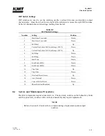
9.2
System Options
The following system options are available at the time of purchase, or as upgrade kits for existing
equipment.
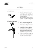
A redundant intensifier allows operation to continue if a problem is detected on the active
intensifier. Operation can be switched to the secondary intensifier until the next
convenient shutdown, when service can be performed on the primary intensifier.
A two liter attenuator is available for 30 and 50 horsepower models. Two liter attenuators
are standard on 60 and 100 horsepower models.
9.3
Operation
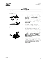
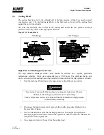
The directional control valve sends pressurized hydraulic oil to one side of the hydraulic cylinder.
The pressurized oil pushes against the piston, moving it in one direction until it activates the
proximity switch at the end of the stroke. The hydraulic flow is then sent to the opposite side of
the cylinder, and the piston reverses direction until it activates the proximity switch at the
opposite end of the stroke.
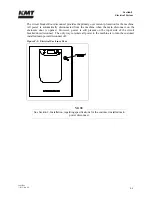
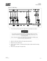
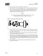
Figure 9-2: High Pressure Water System
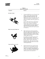
The green light on the proximity switch indicates there is power to the switch. The red light
illuminates when the switch is activated. The proximity switches are magnetically activated by
the presence of the metallic surface of the piston. When the switch is activated, it sends a signal
to the PLC to change the flow of the directional control valve and reverse direction.
As the pressurized oil pushes the piston in one direction, the plunger on that end extends and
pushes against the water in the high pressure cylinder, increasing the pressure up to 60,000 psi
(4,137 bar). When the piston reverses direction, the plunger retracts and the plunger in the
opposite cylinder extends to deliver the high pressure water.
Summary of Contents for Streamline SL-V 100 Plus
Page 60: ...Section 4 Operation 20412948 8 2012 Rev 04 4 19 Figure 4 20 Language Screen ...
Page 179: ...Section 12 Parts List 20413146 8 2012 Rev 12 12 7 Figure 12 2 Intensifier Assembly ...
Page 185: ...Section 12 Parts List 20413146 8 2012 Rev 12 12 13 Figure 12 6 Hydraulic Piston Assembly ...
Page 187: ...Section 12 Parts List 20413146 8 2012 Rev 12 12 15 Figure 12 7 High Pressure Piping ...
Page 191: ...Section 12 Parts List 20413146 8 2012 Rev 12 12 19 Figure 12 9 Hydraulic Power Package ...
Page 193: ...Section 12 Parts List 20413146 8 2012 Rev 12 12 21 Figure 12 10 Motor Pump Assembly ...
Page 195: ...Section 12 Parts List 20413146 8 2012 Rev 12 12 23 Figure 12 11 Hydraulic Manifold Assembly ...
Page 197: ...Section 12 Parts List 20413146 8 2012 Rev 12 12 25 Figure 12 12 Hydraulic Hose Connections ...
Page 199: ...Section 12 Parts List 20413146 8 2012 Rev 12 12 27 Figure 12 13 Reservoir Assembly ...
Page 202: ...Section 12 Parts List 20413146 8 2012 Rev 12 12 30 Figure 12 14 Bulkhead Pipe Assembly ...
Page 203: ......
Page 205: ...Section 12 Parts List 20413146 8 2012 Rev 12 12 32 Figure 12 15 Cover Assembly ...
Page 207: ...Section 12 Parts List 20413146 8 2012 Rev 12 12 34 Figure 12 16 Electrical Assembly ...
Page 210: ...Section 12 Parts List 20413146 8 2012 Rev 12 12 37 Figure 12 17 Controls Subassembly ...
Page 211: ......
Page 217: ...Section 12 Parts List 20413146 8 2012 Rev 12 12 43 Figure 12 20 Proportional Pressure Control ...
Page 219: ...Section 12 Parts List 20413146 8 2012 Rev 12 12 45 Figure 12 21 High Pressure Transducer ...
Page 221: ...Section 12 Parts List 20413146 8 2012 Rev 12 12 47 Figure 12 22 Redundant Kit ...
Page 250: ......
Page 251: ......
Page 252: ......
Page 253: ......
Page 254: ......
Page 255: ......
Page 256: ......
Page 257: ......
Page 258: ......
Page 259: ......
Page 260: ......