


Section 7
Hydraulic System
20412971
8-2012/Rev 08
7-17
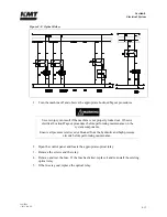
2.
Connect the discharge hose from an oil transfer pump to the fill port and pump the fresh
oil into the reservoir.
NOTE
Oil from a new drum does not meet the cleanliness requirements of the hydraulic
system. For this reason, it is important to use an oil transfer pump that will force
oil through the return filter into the reservoir.
3.
Check the oil sight gauge on the reservoir to ensure proper fill level.
4.
Remove the hose from the case drain on the main hydraulic pump to make sure the pump
case fills with oil. With the hose removed, head pressure from the reservoir will force oil
into the pump case.
Oil in the pump case provides internal lubrication for the main hydraulic pump.
Failure to the fill the pump case with oil will allow air to become trapped inside,
damaging the pump.
5.
Disconnect the discharge hose from the fill port and replace the fill port cap.
6.
Follow the initial startup sequence in Section 4, Operation, to ensure the system fills with
oil.
7.
Check the sight gauge again and follow the same procedure to add additional oil if
necessary.
Electric Motor Bump
Bumping is defined as allowing the electric motor to start rotating, but stopping it before the
motor gets up to full speed.
Whenever the hydraulic reservoir is emptied or the hydraulic pump has been changed, bumping
the electric motor is suggested. This procedure will ensure the hydraulic pump is full of oil and
deter cavitation which will cause the hydraulic pump to fail prematurely.
Do not
perform this procedure until the correct motor rotation and the presence of hydraulic oil in
the hydraulic pump case drain line has been confirmed.
1.
Start the pump in recirculation mode, count two seconds and turn the pump off.
2.
Repeat this process six times before allowing the hydraulic pump to create pressure.
Summary of Contents for Streamline SL-V 100 Plus
Page 60: ...Section 4 Operation 20412948 8 2012 Rev 04 4 19 Figure 4 20 Language Screen ...
Page 179: ...Section 12 Parts List 20413146 8 2012 Rev 12 12 7 Figure 12 2 Intensifier Assembly ...
Page 185: ...Section 12 Parts List 20413146 8 2012 Rev 12 12 13 Figure 12 6 Hydraulic Piston Assembly ...
Page 187: ...Section 12 Parts List 20413146 8 2012 Rev 12 12 15 Figure 12 7 High Pressure Piping ...
Page 191: ...Section 12 Parts List 20413146 8 2012 Rev 12 12 19 Figure 12 9 Hydraulic Power Package ...
Page 193: ...Section 12 Parts List 20413146 8 2012 Rev 12 12 21 Figure 12 10 Motor Pump Assembly ...
Page 195: ...Section 12 Parts List 20413146 8 2012 Rev 12 12 23 Figure 12 11 Hydraulic Manifold Assembly ...
Page 197: ...Section 12 Parts List 20413146 8 2012 Rev 12 12 25 Figure 12 12 Hydraulic Hose Connections ...
Page 199: ...Section 12 Parts List 20413146 8 2012 Rev 12 12 27 Figure 12 13 Reservoir Assembly ...
Page 202: ...Section 12 Parts List 20413146 8 2012 Rev 12 12 30 Figure 12 14 Bulkhead Pipe Assembly ...
Page 203: ......
Page 205: ...Section 12 Parts List 20413146 8 2012 Rev 12 12 32 Figure 12 15 Cover Assembly ...
Page 207: ...Section 12 Parts List 20413146 8 2012 Rev 12 12 34 Figure 12 16 Electrical Assembly ...
Page 210: ...Section 12 Parts List 20413146 8 2012 Rev 12 12 37 Figure 12 17 Controls Subassembly ...
Page 211: ......
Page 217: ...Section 12 Parts List 20413146 8 2012 Rev 12 12 43 Figure 12 20 Proportional Pressure Control ...
Page 219: ...Section 12 Parts List 20413146 8 2012 Rev 12 12 45 Figure 12 21 High Pressure Transducer ...
Page 221: ...Section 12 Parts List 20413146 8 2012 Rev 12 12 47 Figure 12 22 Redundant Kit ...
Page 250: ......
Page 251: ......
Page 252: ......
Page 253: ......
Page 254: ......
Page 255: ......
Page 256: ......
Page 257: ......
Page 258: ......
Page 259: ......
Page 260: ......