


Section 7
Hydraulic System
20412971
8-2012/Rev 08
7-14
8.
Remove the bolts that attach the hydraulic pump to the electric motor.
9.
Support the hydraulic pump and slide it away from the motor, disengaging the flexible
coupling.
10.
Inspect the flexible coupling for damage. If the flexible coupling is damaged it must be
replaced.
11.
Inspect the metal splines on the motor coupling half. Wipe any residue, dirt or oil from
the motor coupling and the flexible coupling. Place the flexible coupling on the motor
coupling half, pushing it on as far as it will go.
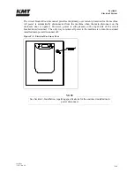
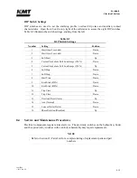
12.
Take a measurement from the front face of the electric motor, the pump mounting
interface, to the outer face of the snap ring or solid band on the flexible coupling,
dimension A.
Figure 7-10: Pump Coupling Dimensions
From dimension A, subtract 5/16 inch for 30, 50 and 60 horsepower motors, and 1/4 inch
for 100 horsepower motors.
13.
Loosen the pinch bolt in the pump coupling half on the old pump and remove the coupling
half. Inspect the metal splines for damage. If the coupling half is not damaged it can be
reused on the new pump.
14.
Wipe any residue, dirt or oil from the pump coupling half. Slide the existing coupling
half, or a new coupling half if necessary, onto the splined shaft of the new pump.
15.
Set the position of the pump coupling half by measuring from the pump mounting face to
the outer face of the coupling teeth, dimension B. On 30, 50 and 60 horsepower models,
B = (A - 0.313), on 100 horsepower models B = (A - 0.250).
16.
Tighten the pinch bolt and torque to 36 ft-lbs (49 Nm) for 30 horsepower models, 63 ft-lbs
(86 Nm) for 50 and 60 horsepower models, and 218 ft-lbs (295 Nm) for 100 horsepower
models.
17.
Place the hydraulic pump on the motor, ensuring the coupling teeth mesh into the flexible
coupling. Force should not be required.
Summary of Contents for Streamline SL-V 100 Plus
Page 60: ...Section 4 Operation 20412948 8 2012 Rev 04 4 19 Figure 4 20 Language Screen ...
Page 179: ...Section 12 Parts List 20413146 8 2012 Rev 12 12 7 Figure 12 2 Intensifier Assembly ...
Page 185: ...Section 12 Parts List 20413146 8 2012 Rev 12 12 13 Figure 12 6 Hydraulic Piston Assembly ...
Page 187: ...Section 12 Parts List 20413146 8 2012 Rev 12 12 15 Figure 12 7 High Pressure Piping ...
Page 191: ...Section 12 Parts List 20413146 8 2012 Rev 12 12 19 Figure 12 9 Hydraulic Power Package ...
Page 193: ...Section 12 Parts List 20413146 8 2012 Rev 12 12 21 Figure 12 10 Motor Pump Assembly ...
Page 195: ...Section 12 Parts List 20413146 8 2012 Rev 12 12 23 Figure 12 11 Hydraulic Manifold Assembly ...
Page 197: ...Section 12 Parts List 20413146 8 2012 Rev 12 12 25 Figure 12 12 Hydraulic Hose Connections ...
Page 199: ...Section 12 Parts List 20413146 8 2012 Rev 12 12 27 Figure 12 13 Reservoir Assembly ...
Page 202: ...Section 12 Parts List 20413146 8 2012 Rev 12 12 30 Figure 12 14 Bulkhead Pipe Assembly ...
Page 203: ......
Page 205: ...Section 12 Parts List 20413146 8 2012 Rev 12 12 32 Figure 12 15 Cover Assembly ...
Page 207: ...Section 12 Parts List 20413146 8 2012 Rev 12 12 34 Figure 12 16 Electrical Assembly ...
Page 210: ...Section 12 Parts List 20413146 8 2012 Rev 12 12 37 Figure 12 17 Controls Subassembly ...
Page 211: ......
Page 217: ...Section 12 Parts List 20413146 8 2012 Rev 12 12 43 Figure 12 20 Proportional Pressure Control ...
Page 219: ...Section 12 Parts List 20413146 8 2012 Rev 12 12 45 Figure 12 21 High Pressure Transducer ...
Page 221: ...Section 12 Parts List 20413146 8 2012 Rev 12 12 47 Figure 12 22 Redundant Kit ...
Page 250: ......
Page 251: ......
Page 252: ......
Page 253: ......
Page 254: ......
Page 255: ......
Page 256: ......
Page 257: ......
Page 258: ......
Page 259: ......
Page 260: ......