


Section 7
Hydraulic System
20412971
8-2012/Rev 08
7-15
18.
Verify that the mating surfaces of the motor and pump meet without resistance from the
coupling.
19.
Replace the pump mounting bolts and torque to the specifications in Table 7-3, Torque
Specifications.
20.
Install the recirculation pump, adapter and booster pump.
21.
Install the hydraulic manifold ensuring that the o-ring is properly positioned. Torque the
mounting bolts to the specifications in Table 7-2.
22.
Reconnect all hydraulic hoses, connections and electrical sensors.
23.
Tighten the hold down screws on the proximity switches and torque to 140-160 in-lbs (16-
18 Nm).
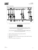
Ensure that the proximity switches are properly installed and secured prior to
starting the motor. Failure to tighten the two hold down screws on each switch
will result in the spray of hydraulic oil.
24.
Refill the hydraulic reservoir following the procedure, Hydraulic Oil Replacement.
25.
Start the motor and apply full high pressure water pressure. Inspect for hydraulic leaks
and note any unusual sounds from the motor or pump assembly.
Table 7-2
Torque Specifications
30 HP
50 and 60 HP
100 HP
Pump mounting bolts
55 ft-lb (75 Nm)
110 ft-lb (149 Nm)
200 ft-lb (271 Nm)
Manifold mounting bolts
35 ft-lb (47 Nm)
35 ft-lb (47 Nm)
45 ft-lb (61 Nm)
Motor coupling half bolts
36 ft-lb (49 Nm)
36 ft-lb (49 Nm)
85 ft-lb (115 Nm)
Electric Motor Replacement
1.
Complete Steps 1-10 in the previous procedure.
2.
Open the junction box on the motor and remove all electrical leads. Loosen the lock nut,
disconnect and remove the flexible electrical cable from the junction box.
3.
Remove the bolts attaching the motor to the vibration isolation mounts and remove the old
motor from the frame.
4.
Stand the new motor on the fan cowl with the shaft pointing upward.
Summary of Contents for Streamline SL-V 100 Plus
Page 60: ...Section 4 Operation 20412948 8 2012 Rev 04 4 19 Figure 4 20 Language Screen ...
Page 179: ...Section 12 Parts List 20413146 8 2012 Rev 12 12 7 Figure 12 2 Intensifier Assembly ...
Page 185: ...Section 12 Parts List 20413146 8 2012 Rev 12 12 13 Figure 12 6 Hydraulic Piston Assembly ...
Page 187: ...Section 12 Parts List 20413146 8 2012 Rev 12 12 15 Figure 12 7 High Pressure Piping ...
Page 191: ...Section 12 Parts List 20413146 8 2012 Rev 12 12 19 Figure 12 9 Hydraulic Power Package ...
Page 193: ...Section 12 Parts List 20413146 8 2012 Rev 12 12 21 Figure 12 10 Motor Pump Assembly ...
Page 195: ...Section 12 Parts List 20413146 8 2012 Rev 12 12 23 Figure 12 11 Hydraulic Manifold Assembly ...
Page 197: ...Section 12 Parts List 20413146 8 2012 Rev 12 12 25 Figure 12 12 Hydraulic Hose Connections ...
Page 199: ...Section 12 Parts List 20413146 8 2012 Rev 12 12 27 Figure 12 13 Reservoir Assembly ...
Page 202: ...Section 12 Parts List 20413146 8 2012 Rev 12 12 30 Figure 12 14 Bulkhead Pipe Assembly ...
Page 203: ......
Page 205: ...Section 12 Parts List 20413146 8 2012 Rev 12 12 32 Figure 12 15 Cover Assembly ...
Page 207: ...Section 12 Parts List 20413146 8 2012 Rev 12 12 34 Figure 12 16 Electrical Assembly ...
Page 210: ...Section 12 Parts List 20413146 8 2012 Rev 12 12 37 Figure 12 17 Controls Subassembly ...
Page 211: ......
Page 217: ...Section 12 Parts List 20413146 8 2012 Rev 12 12 43 Figure 12 20 Proportional Pressure Control ...
Page 219: ...Section 12 Parts List 20413146 8 2012 Rev 12 12 45 Figure 12 21 High Pressure Transducer ...
Page 221: ...Section 12 Parts List 20413146 8 2012 Rev 12 12 47 Figure 12 22 Redundant Kit ...
Page 250: ......
Page 251: ......
Page 252: ......
Page 253: ......
Page 254: ......
Page 255: ......
Page 256: ......
Page 257: ......
Page 258: ......
Page 259: ......
Page 260: ......