


Section 1
Introduction
20412914
8-2012/Rev 09
1-5
1.4
Safety
The high pressure waterjet cutting system is a high energy cutting tool capable of cutting many
dense or strong materials. Do not touch or be exposed to high pressure water. High pressure
water will penetrate all parts of the human body. The liquid stream and the material ejected by
the extreme pressure can result in severe injury.
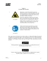
All personnel operating, servicing or working near the waterjet cutting equipment shall adhere to
the following safety precautions, as well as the applicable plant safety precautions.
Only KMT factory trained, qualified personnel shall service and maintain the
equipment.
The operator shall practice and promote safety at all times to avoid potential
injury and unnecessary downtime.
The work area around the equipment shall be clean and free of debris and oil
spills.
All protective guards, shields or covers shall be in place on the equipment at
all times.
Safety glasses and ear protection shall be worn when operating or
working near the equipment.
Lockout/Tagout Procedure
This lockout/tagout procedure is designed to protect all employees from injuries caused by the
unexpected energizing or startup of the machine, or the release of stored energy during service
and maintenance.
This is accomplished with energy isolating devices that prevent the transmission or release of
energy. An energy source is any source of electrical, mechanical, hydraulic, pneumatic,
chemical, thermal, or other energy source that could cause injury to personnel.
A lockout device utilizes a lock and key to hold an energy isolating device in the safe position
and prevents the machine from being energized. A tagout device is a prominent warning device
that can be securely attached to the machine warning personnel not to operate the energy isolating
device. This procedure requires the combination of a lockout device and a tagout device.
The lockout/tagout procedure applies to any employee who operates and/or performs service or
maintenance on the machine. Before any maintenance or repairs are performed, the machine
shall be isolated, and rendered inoperative as follows.
1.
Shut down the machine by pressing the stop button, and open the high pressure cutting
water valve to bleed the water and hydraulic pressure from the system.
2.
Disconnect, lockout and tag the main, customer supplied, power source.
3.
Lockout and tag the circuit breaker/disconnect on the electrical enclosure door.
Summary of Contents for Streamline SL-V 100 Plus
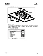
Page 60: ...Section 4 Operation 20412948 8 2012 Rev 04 4 19 Figure 4 20 Language Screen ...
Page 179: ...Section 12 Parts List 20413146 8 2012 Rev 12 12 7 Figure 12 2 Intensifier Assembly ...
Page 185: ...Section 12 Parts List 20413146 8 2012 Rev 12 12 13 Figure 12 6 Hydraulic Piston Assembly ...
Page 187: ...Section 12 Parts List 20413146 8 2012 Rev 12 12 15 Figure 12 7 High Pressure Piping ...
Page 191: ...Section 12 Parts List 20413146 8 2012 Rev 12 12 19 Figure 12 9 Hydraulic Power Package ...
Page 193: ...Section 12 Parts List 20413146 8 2012 Rev 12 12 21 Figure 12 10 Motor Pump Assembly ...
Page 195: ...Section 12 Parts List 20413146 8 2012 Rev 12 12 23 Figure 12 11 Hydraulic Manifold Assembly ...
Page 197: ...Section 12 Parts List 20413146 8 2012 Rev 12 12 25 Figure 12 12 Hydraulic Hose Connections ...
Page 199: ...Section 12 Parts List 20413146 8 2012 Rev 12 12 27 Figure 12 13 Reservoir Assembly ...
Page 202: ...Section 12 Parts List 20413146 8 2012 Rev 12 12 30 Figure 12 14 Bulkhead Pipe Assembly ...
Page 203: ......
Page 205: ...Section 12 Parts List 20413146 8 2012 Rev 12 12 32 Figure 12 15 Cover Assembly ...
Page 207: ...Section 12 Parts List 20413146 8 2012 Rev 12 12 34 Figure 12 16 Electrical Assembly ...
Page 210: ...Section 12 Parts List 20413146 8 2012 Rev 12 12 37 Figure 12 17 Controls Subassembly ...
Page 211: ......
Page 217: ...Section 12 Parts List 20413146 8 2012 Rev 12 12 43 Figure 12 20 Proportional Pressure Control ...
Page 219: ...Section 12 Parts List 20413146 8 2012 Rev 12 12 45 Figure 12 21 High Pressure Transducer ...
Page 221: ...Section 12 Parts List 20413146 8 2012 Rev 12 12 47 Figure 12 22 Redundant Kit ...
Page 250: ......
Page 251: ......
Page 252: ......
Page 253: ......
Page 254: ......
Page 255: ......
Page 256: ......
Page 257: ......
Page 258: ......
Page 259: ......
Page 260: ......