


Section 9
High Pressure Water System
20412997
8-2012/Rev 12
9-11
High Pressure Cylinder Assembly Removal
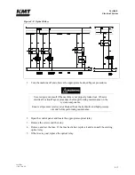
Prior to removing electrical power or any high or low pressure piping, start the machine from the
Maintenance Screen on the control panel. The machine will start in recirculation mode; the dump
valve will open and relieve the high pressure in the system.
Press the right or left arrow to extend the plunger on the end to be serviced. The plunger will
extend in the selected direction, allowing full exposure when the unit is disassembled.
1.
Turn the machine off and observe the appropriate Lockout/Tagout procedures.
Severe injury can result if the machine is not properly locked out. Observe
electrical Lockout/Tagout procedures before proceeding.
Ensure all pressure is relieved or blocked from the hydraulic and high pressure
circuits before proceeding.
2.
Disconnect the high and low pressure water piping, following the procedure, High and
Low Pressure Water Piping.
NOTE
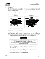
Prior to removal, verify that the alignment marks on the high pressure cylinder and
on the hydraulic cylinder head are aligned. If not, check the condition of the
retaining ring and the bushing retainer flange after the cylinder assembly is
removed.
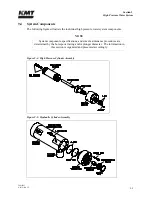
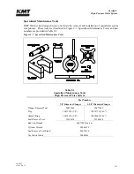
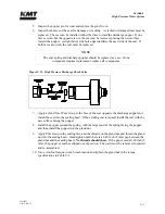
Due to the weight of the cylinder assembly, adequate support must be provided to
prevent damage to the plunger or seals during removal and installation. See Figure
9-7, Specialized Maintenance Tools for tools available to support the high pressure
assembly for this procedure.
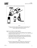
3.
Position the vee block cradle tool under the cylinder assembly. Unthread and remove the
assembly from the hydraulic cylinder head and plunger. The assembly can be rotated with
the cylinder wrench or by hand.
Summary of Contents for Streamline SL-V 100 Plus
Page 60: ...Section 4 Operation 20412948 8 2012 Rev 04 4 19 Figure 4 20 Language Screen ...
Page 179: ...Section 12 Parts List 20413146 8 2012 Rev 12 12 7 Figure 12 2 Intensifier Assembly ...
Page 185: ...Section 12 Parts List 20413146 8 2012 Rev 12 12 13 Figure 12 6 Hydraulic Piston Assembly ...
Page 187: ...Section 12 Parts List 20413146 8 2012 Rev 12 12 15 Figure 12 7 High Pressure Piping ...
Page 191: ...Section 12 Parts List 20413146 8 2012 Rev 12 12 19 Figure 12 9 Hydraulic Power Package ...
Page 193: ...Section 12 Parts List 20413146 8 2012 Rev 12 12 21 Figure 12 10 Motor Pump Assembly ...
Page 195: ...Section 12 Parts List 20413146 8 2012 Rev 12 12 23 Figure 12 11 Hydraulic Manifold Assembly ...
Page 197: ...Section 12 Parts List 20413146 8 2012 Rev 12 12 25 Figure 12 12 Hydraulic Hose Connections ...
Page 199: ...Section 12 Parts List 20413146 8 2012 Rev 12 12 27 Figure 12 13 Reservoir Assembly ...
Page 202: ...Section 12 Parts List 20413146 8 2012 Rev 12 12 30 Figure 12 14 Bulkhead Pipe Assembly ...
Page 203: ......
Page 205: ...Section 12 Parts List 20413146 8 2012 Rev 12 12 32 Figure 12 15 Cover Assembly ...
Page 207: ...Section 12 Parts List 20413146 8 2012 Rev 12 12 34 Figure 12 16 Electrical Assembly ...
Page 210: ...Section 12 Parts List 20413146 8 2012 Rev 12 12 37 Figure 12 17 Controls Subassembly ...
Page 211: ......
Page 217: ...Section 12 Parts List 20413146 8 2012 Rev 12 12 43 Figure 12 20 Proportional Pressure Control ...
Page 219: ...Section 12 Parts List 20413146 8 2012 Rev 12 12 45 Figure 12 21 High Pressure Transducer ...
Page 221: ...Section 12 Parts List 20413146 8 2012 Rev 12 12 47 Figure 12 22 Redundant Kit ...
Page 250: ......
Page 251: ......
Page 252: ......
Page 253: ......
Page 254: ......
Page 255: ......
Page 256: ......
Page 257: ......
Page 258: ......
Page 259: ......
Page 260: ......