


Section 9
High Pressure Water System
20412997
8-2012/Rev 12
9-42
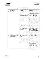
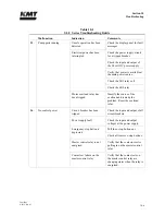
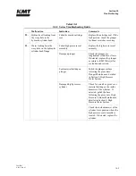
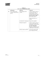
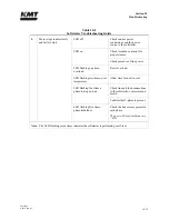
Table 9-3
Weep Holes
High Pressure Water System
Location Indication Comments
Sealing Head
Water leaking from the weep
hole in the sealing head
Seat in the discharge check valve
is not sealing properly
Make sure the gland nut is
tightened to the proper torque
specification.
Inspect the seat, sealing head and
gland nut for cracks.
Internal crack in sealing head
Replace the sealing head.
A cracked sealing head can result
in water leaking from the high
pressure outlet passage to the low
pressure inlet passages.
The sealing head body can
become extremely hot.
Improper torque on gland nut
Tighten the gland nut to the
proper torque specification.
Erosion or scratches on the
contact surface of the sealing
head, or on the gland nut where
the seat makes contact
Polish the surfaces following the
procedure, Sealing Head
Maintenance.
Water leaking from the weep
hole in the gland nut
High pressure piping gland nut is
not tight and is not sealing
properly
Tighten the gland nut to the
proper torque specification.
Improper high pressure piping
connection
Check the number of exposed
threads past the collar on the high
pressure piping. Only 1-1/2 to 2-
1/2 threads should be exposed.
Check high pressure piping for
damage, cracks or deformation.
Inspect the gland nut for
deformation of the threads.
Damaged sealing head gland nut
Check the gland nut for cracks
due to fatigue. If cracks are
detected, replace the gland nut.
Summary of Contents for Streamline SL-V 100 Plus
Page 60: ...Section 4 Operation 20412948 8 2012 Rev 04 4 19 Figure 4 20 Language Screen ...
Page 179: ...Section 12 Parts List 20413146 8 2012 Rev 12 12 7 Figure 12 2 Intensifier Assembly ...
Page 185: ...Section 12 Parts List 20413146 8 2012 Rev 12 12 13 Figure 12 6 Hydraulic Piston Assembly ...
Page 187: ...Section 12 Parts List 20413146 8 2012 Rev 12 12 15 Figure 12 7 High Pressure Piping ...
Page 191: ...Section 12 Parts List 20413146 8 2012 Rev 12 12 19 Figure 12 9 Hydraulic Power Package ...
Page 193: ...Section 12 Parts List 20413146 8 2012 Rev 12 12 21 Figure 12 10 Motor Pump Assembly ...
Page 195: ...Section 12 Parts List 20413146 8 2012 Rev 12 12 23 Figure 12 11 Hydraulic Manifold Assembly ...
Page 197: ...Section 12 Parts List 20413146 8 2012 Rev 12 12 25 Figure 12 12 Hydraulic Hose Connections ...
Page 199: ...Section 12 Parts List 20413146 8 2012 Rev 12 12 27 Figure 12 13 Reservoir Assembly ...
Page 202: ...Section 12 Parts List 20413146 8 2012 Rev 12 12 30 Figure 12 14 Bulkhead Pipe Assembly ...
Page 203: ......
Page 205: ...Section 12 Parts List 20413146 8 2012 Rev 12 12 32 Figure 12 15 Cover Assembly ...
Page 207: ...Section 12 Parts List 20413146 8 2012 Rev 12 12 34 Figure 12 16 Electrical Assembly ...
Page 210: ...Section 12 Parts List 20413146 8 2012 Rev 12 12 37 Figure 12 17 Controls Subassembly ...
Page 211: ......
Page 217: ...Section 12 Parts List 20413146 8 2012 Rev 12 12 43 Figure 12 20 Proportional Pressure Control ...
Page 219: ...Section 12 Parts List 20413146 8 2012 Rev 12 12 45 Figure 12 21 High Pressure Transducer ...
Page 221: ...Section 12 Parts List 20413146 8 2012 Rev 12 12 47 Figure 12 22 Redundant Kit ...
Page 250: ......
Page 251: ......
Page 252: ......
Page 253: ......
Page 254: ......
Page 255: ......
Page 256: ......
Page 257: ......
Page 258: ......
Page 259: ......
Page 260: ......