background image

KLARO GmbH

Original Operating Manual for KLARO Small Wastewater Treatment Plant V.15.07

53

4.

 Installation

(bei der Anwendung zur

Wasserrein

igung/Belüftung)

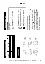
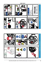
1. Standortauswahl für den Aufbau/Einbau

1.

Verfahrensweise beim Aufbau/Einbau

3. Inbetriebnahme

1. S

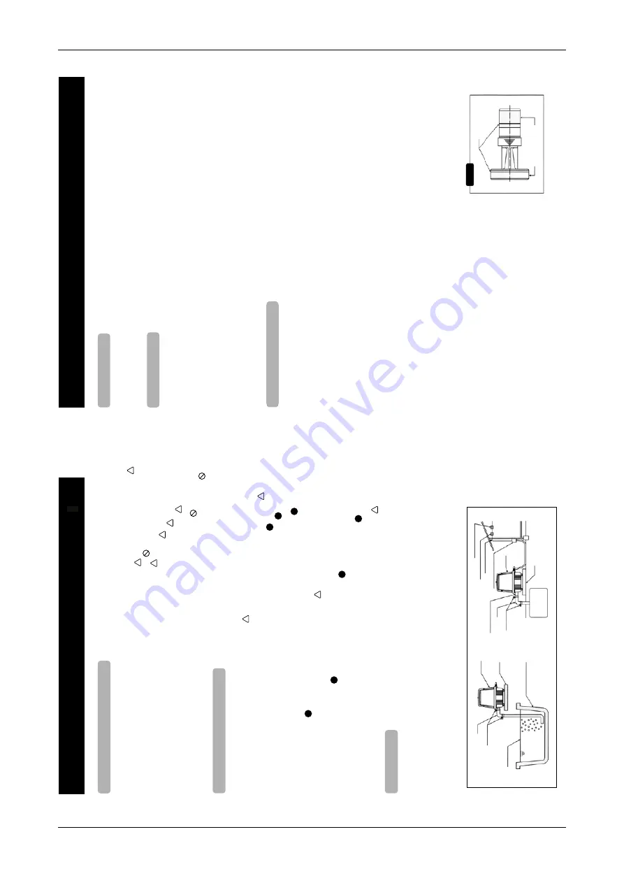
tellen Sie den Belüfter in der Nähe des Klärbehälters/Aquariums au

f. W

enn die Luftzuleitung lang ist,

    bringt di

e Abwa

sseraufb

ereitung

nicht die volle L

eistung, aufgrund einer ungenügenden Luftströmung.

2. I

nstallieren Sie den Belüfter an einer für die 

Wartung

geeigneten Stelle

.

3. B

auen Sie den Belüfter auf einem f

esten und horizontalen Untergrund auf

.

4. S

tellen Sie den Belüfter an einem wind-und staubgeschützten Ort auf

.

5. S

tellen Sie sicher

, dass Sie den Belüfter an einer gut belüfteten

Stelle aufstellen.

6. I

nstallieren Sie den Belüfter mindestens 30 Zentimeter

von ein

er Haus

wand en

tfernt.

7. D

ie Installation an einer schattigen Stelle ist empfehle

nswe

rt, um die Hit

zeerze

ugung des

    Belüfters zu reduzieren.

8. I

nstallieren Sie den Belüfter an einer Stelle, a

n welche

r er nicht überflutet werden

 kann.

9. I

nstallieren Sie den Belüfter nicht an einer Stelle mit übermäßiger Feuchtigk

eit oder Luftfeuc

htigkeit

.

  1. 

Der Unterg

rund sollte a

us Material b

estehen das fest g

enug ist u

m das Ge

wicht zu tr

agen

      und um die V

ibrationen

 des Belüfters abzub

locken

.

  2. 

Der Unterg

rund des Be

lüfters sollte mindestens 10 Zentimeter über dem 

Wasse

rspiegel

      sein so

wie eine Größe haben die 5 Zentimeter über den äußeren Maßen des Belüfters liegt.

  3. 

Sorgen Sie für eine separate St

eckdose

 welche n

ur für den Belüfter benutzt wird

.

  4. 

Elektrische A

rbeiten müssen vo

n einem qualifizierten Elek

triker durchgeführt werd

en.

  5. 

Die Stromv

ersorgung sollte der

, auf dem Etikett des

 Belüfters

, vorgeg

ebenen Spannung

      entsprechen und mit einer Erdung sowi

e einem Überspann

ungsschutz montiert sein

.

  6. 

Die benut

zte Stec

kdose sollte wasser

dicht sein sowie eine

 entsprechende

Verbindung

mit der 

      Erdung aufweise

n.

  7. 

Stellen Sie den Belüfter horizontal auf dem Untergrund auf.

  8. 

Benutze

n Sie einen flexib

len Gummischlauch für die 

Verbindung

zwischen dem Luftauslass

      des Belüfters und der Leitung.

  9. 

Der Gummischlauch m

uss mit Schlauchschellen bef

estigt wer

den.

10.

Wenn S

ie die 

Verbindung

herstellen, dann bringe

n Sie den Luftauslass

auf gleiche Höhe mit

      der Leitung, um sicher zu gehen dass der Schlauch nicht b

lockiert oder 

verknotet

 ist.

11.

Bevo

r Sie den Belüfter starten, 

gehen Sie sicher dass die W

asserhöhe im Klärbehälter/

      Aquarium

 angemessen ist (siehe 1.)  und dass die 

Ventile der Leitung richtig

 offen s

ind.

Stecken Sie den Netzstecker des Belüfters mit v

ollständigem Kontakt in die Steckdose, so

dass der Stecker nicht wack

elt.

Eine unvollständige 

Verbindung kann einen Stromschlag oder ein F

euer zur Folge haben.

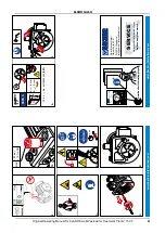
Stellen Sie nach der Inbetriebnahme folgende Punkte sicher :

Es darf kein Luftleck am Schlauch oder an der 

Verbindung zur Leitung v

orhanden sein.

Die Leitung zwischen Belüfter und Klärbehälter/Aquariums darf nicht zu stark gespannt sein, 

um eine Vibration des Untergrunds zu vermeiden.

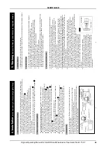
Belüfter

Untergrund

Schlauch

Schlauchschellen

Wasserhöhe

Wassertank oder T

eich

Luftauslass des Belüfters

Belüfter

Untergrund

Schlauch

Schlauchschellen

Überspannungsschutz

Erdungsverbindung

Stromleitung

Wassergeschützte Steckdose mit Erdung

Belüfteter Abwassertank

!

!

!

!

!

!

!

!

!

!

!

!

!

!

!

!

!

-4-

5.

W

artung

(Nehmen Sie Bezug auf die Skizzen

 der f

olgende

n Seiten)

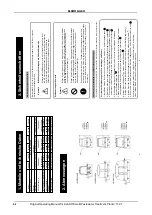
1. Sicherheitshinweise

2. Austausch der Filter

3. Austausch des K

olbensatzes

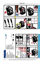
1. MEDO Belüfter sind ölfrei.

 Ölen Sie die Belüfter niemals.

2. Alle Belüfter sind präzise justiert worden.

 Öffnen Sie die Sechskantschrauben am Pumpenende niemals. 

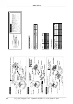
1. Stellen Sie sicher dass der Belüfter ausgesteckt ist, be

vor Sie mit den Austauscharbeiten beginnen

2. Lösen Sie die Schrauben (n) 1 und nehmen Sie den Gehäusedec

kel 4 ab.

3. Entfernen Sie den Filter 5 aus dem Gehäuse 6 und setzen Sie einen neuen Filter ein.

    Zugleich reinigen Sie den Lufteinlass des Gehäusedeckels 4 und des Gehäuseoberteils 6.

4. Setzen Sie den Gehäusedec

kel 4 genau passend mit der Filterdeckeldichtung 3 zusammen.

5. Montieren Sie den Gehäusedeck

el 4 mit dem Gehäuseoberteil 6, 

    danach ziehen Sie die Schrauben(n) 1 fest.

6. Empfohlener Zeitpunkt um den Filte

r auszutauschen :

    Wann der Filter gereinigt oder ersetzt w

erden soll, ist abhängig von dem Ausmaß der 

Verschmutzung,

    welche durch die athmosphärischen Bedingungen rund um die Anwendung verursacht wird.

    Der Zustand des Filters sollte alle drei Monate geprüft werden.

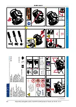
1. Stellen Sie sicher dass der Belüfter ausgesteckt ist, be

vor Sie mit den W

artungsarbeiten beginnen.

2. Entfernen Sie das Gehäuseoberteil 6, lösen Sie dann alle Sechskantschrauben 9

    des V

ordergehäuses 10 und entfernen Sie diesen. F

alls das V

ordergehäuse sich nicht lösen

    lässt, dann setzen Sie einen Schraubendreher in der Nut am Rand des V

ordergehäuses 10 an,

    und drehen den Schraubendreher vorsichtig, um das V

ordergehäuse entfernen zu können.

3. Nehmen Sie den kompletten K

olben heraus.

4. Ersetzen, Sie die Dichtung A11 und die Dichtung B12 mit neuen Dichtungen.

 Stellen Sie sicher,

    dass die T

eflonschicht des Kolbens 13 nicht mit Staub, Spänen, 

Wasser, Öl oder Schmierf

ett in 

    Berührung kommt. 

Vermeiden Sie es die 

Teflonschicht des Kolbens 13 mit den Fingern zu berühren.

5. Setzen Sie den K

olben in das Pumpengehäuse ein. Setzen Sie Dichtung A11 in den Gehäusedec

kel

    und Dichtung B12 am Pumpengehäuse ein, dann befestigen Sie das V

ordergehäuse 10 mit den

    Sechskantschrauben 9. Ziehen Sie die Sechskantschrauben 9 nach und nach so

wie abwechselnd an, 

    bevor Sie sie vollständig f

estdrehen.

6. Bev

or Sie das Gehäuseoberteil 6 wieder einsetzen, starten Sie den Belüfter und prüfen das

    V

ordergehäuse 10 und die Dichtung 33 nach Luftlecks, indem Sie den Luftauslass vorsichtig 

    blockieren.

 Im Falle eines Luftlecks entlang des 

Vordergehäuses 10, setz

en Sie die Dichtung A11

    und die Dichtung B12 nochmal ein und ziehen die Sechskantschrauben 9 noch einmal fest.     Falls ein Luftleck an der Dichtung 33 v

orhanden ist, prüfen Sie ob die Dichtung richtig am Lufttank 

    eingesetzt ist und drücken Sie danach das Pumpengehäuse nach unten, damit der Luftauslassstutzen     des Gehäusedeckels richtig in die Lochführung der Dichtung eingeführt wird.

7. Nachdem Sie die Dichtung C8 korrekt auf das Gehäuseunterteil 

    eingesetzt haben, setzen Sie das Gehäuseoberteil 6 wieder ein. 

    Ziehen Sie die T

orx-Schrauben 7 gleichmäßig und abwechselnd 

    wieder fest.

8. Empfohlener Zeitpunkt um den K

olbensatz zu ersetzen :

    Es wird empfohlen, dass der Kolbensatz alle 12 bis 24 Monate 

    ersetzt wird, was abhängig ist von dem Druckverlust und dem 

    V

erlust der Luftfördermenge. An jeder T

eflonschicht des Kolbens 

    ist eine Einkerbung vorhanden.

 Diese Einkerbungen zeigen den 

    Grad der Abnutzung an. Sobald eine oder beide Eink

erbungen

    nicht mehr vorhanden sind, ist die Ersetzung des Kolbensatzes 

    empfehlenswert.

-5-

Einkerbungen

Teflonschicht

ü

ö

ü

ä

ü

ä

ä

ä

ö

ü

ü

ü

ü

ü

ü

ü

ü

ü

ü ü

ü

ü

ü

ä

ü

ü

ü

ü

ü

ü

ü

ü

Ü

ü

ü

ö

ü

ü

ö

ä

ä

ü

ü

ä

ä

ä

ä

ü

ü

ü

ü

ü

ö

Ö

ä

Ö

ö

ä

ä

ä

ä

ä

ä

ä

ä

ä

ü

ü

ö

ä

ä

ä

ö

ä

ä

ä

ö

Ö

ä

ü

ü

ä

ä

ä

ä

ä ä

ü

ü

ä

ä

ü

ü

ä

ä

ü

ü

ä

ä

ä

ä

ö

ü

ü

ü

ü

Ü

ö

ü

ü

ß

ß

ß

ß

KLARO GmbH

2

Original Operating Manual for KLARO Small Wastewater Treatment Plant V.15.07

IMPORTANT: 

This Operating Manual contains information about the plant, from installation 

to maintenance, and must therefore be read before commissioning of the 

plant!

All safety instructions must be observed!

The Operating Manual must be kept readily available during the operation of 

the plant!

Plant Specifications

For any questions in the course of the operation of the plant, the specifications of your plant should 
be noted as follows. With the help of this information, our staff will be able to help you more quickly 
in the event of a malfunction. The specifications can be found on the nameplate, which is located 
on the outside of the cabinet door for indoor cabinets, and inside the cabinet for outdoor cabinets.

Small Wastewater Treatment 

Plant

PT

Sludge storage

Buffer

SB-Reactor

Approval No.:

Process class:

Certified:

Cabinet:

Controller:

Compressor: 

Denomination:

Serial No.:

Article No.:

Additional module:

Article No.:

El. Connected load:

KLARO GmbH

Original Operating Manual for KLARO Small Wastewater Treatment Plant V.15.07

3

CONTENTS

Page

1.


About this Operating Manual

6


1.1.


Original Language of Documentation

6


1.2.


Completeness

6


1.3.


Liability

7


2.


Safety

7


2.1.


Explanation of Warnings and Prohibitions

7


2.2.


Hazard statements

8


2.3.


Warnings

9


2.4.


Exclusion for Use

10


3.


Warranty

10


4.


Function of the SBR Plant

10


4.1.


Plants for carbon elimination (process classes C)

11


4.2.


Systems with Additional Nitrogen Removal (Process Classes N and D)

13


4.3.


Systems with Additional Phosphate Elimination (Process Class +P)

13


4.4.


Systems with Additional Sanitation (Process Class +S)

13


5.


Control of the Small Wastewater Treatment Plant

13


5.1.


Connections to the KL-controls (230V option for solenoid valves)

16


5.2.


Connections to the KL24 controller(24V option for stepper motor valves)

16


5.3.


Operating the Controller

18


5.3.1.


Querying Operating Hours

18


5.3.2.


Manual Control of the Valves and the Cabinet Fan in "Manual Mode"

19


5.3.3.


Setting Date/Time

20


5.3.4.


Set Holiday Mode

20


5.3.5.


Query Malfunctions - Query Old Malfunctions

21


5.3.6.


Display Settings

21


5.3.7.


Service Menu and Action Code

21


5.4.


Changing the Fuses

22


5.5.


Operation of Power Failure Detector

22


6.


Additional functions of the Controllers KLplus/ KL24plus and KLbasic/KL24base

23


6.1.


Underload detection (KLplus/KL24plus)

23


6.1.1.


Mode of Operation

24


6.1.2.


Commissioning

24


6.1.3.


Switching Off the Level Measurement

25


6.1.4.


Safety and Fault Messages

25


6.2.


Optional Functions

26


6.2.1.


Connection of an external alarm device

26


6.2.2.


Connection of a contactor for switching the compressor

26


6.2.3.


Connection of a UV reactor

26


6.2.4.


Phosphate precipitation with metering pump

26


7.


Maintenance, Repair and Operation

28


7.1.


Sludge Evacuation

28


7.2.


Operating Instructions

29


8.


Fault Messages and Troubleshooting

31


8.1.


Fault Message on the Display

32


8.2.


Unusual Water Levels - Troubleshooting

33


KLARO GmbH

2

Original Operating Manual for KLARO Small Wastewater Treatment Plant V.15.07

IMPORTANT: 

This Operating Manual contains information about the plant, from installation 

to maintenance, and must therefore be read before commissioning of the 

plant!

All safety instructions must be observed!

The Operating Manual must be kept readily available during the operation of 

the plant!

Plant Specifications

For any questions in the course of the operation of the plant, the specifications of your plant should 
be noted as follows. With the help of this information, our staff will be able to help you more quickly 
in the event of a malfunction. The specifications can be found on the nameplate, which is located 
on the outside of the cabinet door for indoor cabinets, and inside the cabinet for outdoor cabinets.

Small Wastewater Treatment 

Plant

PT

Sludge storage

Buffer

SB-Reactor

Approval No.:

Process class:

Certified:

Cabinet:

Controller:

Compressor: 

Denomination:

Serial No.:

Article No.:

Additional module:

Article No.:

El. Connected load:

KLARO GmbH

Original Operating Manual for KLARO Small Wastewater Treatment Plant V.15.07

3

CONTENTS

Page

1.


About this Operating Manual

6


1.1.


Original Language of Documentation

6


1.2.


Completeness

6


1.3.


Liability

7


2.


Safety

7


2.1.


Explanation of Warnings and Prohibitions

7


2.2.


Hazard statements

8


2.3.


Warnings

9


2.4.


Exclusion for Use

10


3.


Warranty

10


4.


Function of the SBR Plant

10


4.1.


Plants for carbon elimination (process classes C)

11


4.2.


Systems with Additional Nitrogen Removal (Process Classes N and D)

13


4.3.


Systems with Additional Phosphate Elimination (Process Class +P)

13


4.4.


Systems with Additional Sanitation (Process Class +S)

13


5.


Control of the Small Wastewater Treatment Plant

13


5.1.


Connections to the KL-controls (230V option for solenoid valves)

16


5.2.


Connections to the KL24 controller(24V option for stepper motor valves)

16


5.3.


Operating the Controller

18


5.3.1.


Querying Operating Hours

18


5.3.2.


Manual Control of the Valves and the Cabinet Fan in "Manual Mode"

19


5.3.3.


Setting Date/Time

20


5.3.4.


Set Holiday Mode

20


5.3.5.


Query Malfunctions - Query Old Malfunctions

21


5.3.6.


Display Settings

21


5.3.7.


Service Menu and Action Code

21


5.4.


Changing the Fuses

22


5.5.


Operation of Power Failure Detector

22


6.


Additional functions of the Controllers KLplus/ KL24plus and KLbasic/KL24base

23


6.1.


Underload detection (KLplus/KL24plus)

23


6.1.1.


Mode of Operation

24


6.1.2.


Commissioning

24


6.1.3.


Switching Off the Level Measurement

25


6.1.4.


Safety and Fault Messages

25


6.2.


Optional Functions

26


6.2.1.


Connection of an external alarm device

26


6.2.2.


Connection of a contactor for switching the compressor

26


6.2.3.


Connection of a UV reactor

26


6.2.4.


Phosphate precipitation with metering pump

26


7.


Maintenance, Repair and Operation

28


7.1.


Sludge Evacuation

28


7.2.


Operating Instructions

29


8.


Fault Messages and Troubleshooting

31


8.1.


Fault Message on the Display

32


8.2.


Unusual Water Levels - Troubleshooting

33


53

Summary of Contents for LA-100

Page 1: ...ro d u c t s M ade in Germ a n y Operating manual for KLARO small wastewater treatment plants We provide clean water No mechanical parts in the wastewater No pumps in the wastewater No electrical part...

Page 2: ...questions in the course of the operation of the plant the specifications of your plant should be noted as follows With the help of this information our staff will be able to help you more quickly in t...

Page 3: ...ontroller 18 5 3 1 Querying Operating Hours 18 5 3 2 Manual Control of the Valves and the Cabinet Fan in Manual Mode 19 5 3 3 Setting Date Time 20 5 3 4 Set Holiday Mode 20 5 3 5 Query Malfunctions Qu...

Page 4: ...RO GmbH 2 Original Operating Manual for KLARO Small Wastewater Treatment Plant V 15 07 IMPORTANT This Operating Manual contains information about the plant from installation to maintenance and must th...

Page 5: ...6 1 1 Mode of Operation 24 6 1 2 Commissioning 24 6 1 3 Switching Off the Level Measurement 25 6 1 4 Safety and Fault Messages 25 6 2 Optional Functions 26 6 2 1 Connection of an external alarm devic...

Page 6: ...MoAnl 19 Factory Calibration Controller MoAnl 20 Submersible Pump for Additional Buffer Date of print 06 2015 KLARO GmbH 2 Original Operating Manual for KLARO Small Wastewater Treatment Plant V 15 07...

Page 7: ...rs KLplus KL24plus and KLbasic KL24base 23 6 1 Underload detection KLplus KL24plus 23 6 1 1 Mode of Operation 24 6 1 2 Commissioning 24 6 1 3 Switching Off the Level Measurement 25 6 1 4 Safety and Fa...

Page 8: ...s be left running except for maintenance purposes because proper wastewater treatment cannot be ensured otherwise KLARO GmbH 2 Original Operating Manual for KLARO Small Wastewater Treatment Plant V 15...

Page 9: ...al Mode 19 5 3 3 Setting Date Time 20 5 3 4 Set Holiday Mode 20 5 3 5 Query Malfunctions Query Old Malfunctions 21 5 3 6 Display Settings 21 5 3 7 Service Menu and Action Code 21 5 4 Changing the Fuse...

Page 10: ...system essentially consists of 2 stages A sludge storage with integrated pre buffer and an activated sludge stage in a closed sequencing batch reactor SBR The upstream sludge storage with integrated b...

Page 11: ...oliday Mode 20 5 3 5 Query Malfunctions Query Old Malfunctions 21 5 3 6 Display Settings 21 5 3 7 Service Menu and Action Code 21 5 4 Changing the Fuses 22 5 5 Operation of Power Failure Detector 22 6...

Page 12: ...o holiday mode The holiday mode is a greatly reduced operating mode of the plant during longer periods without wastewater inflow Figure 1 Membrane Tube Diffusor Figure 2 Membrane Plate Diffusor KLARO...

Page 13: ...07 3 CONTENTS Page 1 About this Operating Manual 6 1 1 Original Language of Documentation 6 1 2 Completeness 6 1 3 Liability 7 2 Safety 7 2 1 Explanation of Warnings and Prohibitions 7 2 2 Hazard stat...

Page 14: ...tion about the plant from installation to maintenance and must therefore be read before commissioning of the plant All safety instructions must be observed The Operating Manual must be kept readily av...

Page 15: ...6 1 1 Mode of Operation 24 6 1 2 Commissioning 24 6 1 3 Switching Off the Level Measurement 25 6 1 4 Safety and Fault Messages 25 6 2 Optional Functions 26 6 2 1 Connection of an external alarm devic...

Page 16: ...riginal Operating Manual for KLARO Small Wastewater Treatment Plant V 15 07 IMPORTANT This Operating Manual contains information about the plant from installation to maintenance and must therefore be...

Page 17: ...22 6 Additional functions of the Controllers KLplus KL24plus and KLbasic KL24base 23 6 1 Underload detection KLplus KL24plus 23 6 1 1 Mode of Operation 24 6 1 2 Commissioning 24 6 1 3 Switching Off t...

Page 18: ...be read before commissioning of the plant All safety instructions must be observed The Operating Manual must be kept readily available during the operation of the plant Plant Specifications For any q...

Page 19: ...e Valves and the Cabinet Fan in Manual Mode 19 5 3 3 Setting Date Time 20 5 3 4 Set Holiday Mode 20 5 3 5 Query Malfunctions Query Old Malfunctions 21 5 3 6 Display Settings 21 5 3 7 Service Menu and...

Page 20: ...19 12 2015 Mo 20 15 56 20 15 Mo 19 12 15 KLARO GmbH 2 Original Operating Manual for KLARO Small Wastewater Treatment Plant V 15 07 IMPORTANT This Operating Manual contains information about the plant...

Page 21: ...e KL controls 230V option for solenoid valves 16 5 2 Connections to the KL24 controller 24V option for stepper motor valves 16 5 3 Operating the Controller 18 5 3 1 Querying Operating Hours 18 5 3 2 M...

Page 22: ...rogram settings etc is saved However if no time and date is set no weekly operating hours of the units will be saved Future fault messages will be saved with an incorrect date KLARO GmbH 2 Original Op...

Page 23: ...astewater Treatment Plant 13 5 1 Connections to the KL controls 230V option for solenoid valves 16 5 2 Connections to the KL24 controller 24V option for stepper motor valves 16 5 3 Operating the Contr...

Page 24: ...ICE CODE INPUT press the key and enter the following code when prompted 9 9 9 9 Calibrate No Use the arrow keys to select CALIBRATE YES and confirm with the key and start the calibration Figure 11 Cha...

Page 25: ...Process Classes N and D 13 4 3 Systems with Additional Phosphate Elimination Process Class P 13 4 4 Systems with Additional Sanitation Process Class S 13 5 Control of the Small Wastewater Treatment Pl...

Page 26: ...chloride and ethylene oxide there is a hazard of explosion Consult the appropriate Material Safety Data Sheet before using phosphate precipitants Wear protective clothing when handling poly aluminium...

Page 27: ...he KL24 controller 24V option for stepper motor valves 16 5 3 Operating the Controller 18 5 3 1 Querying Operating Hours 18 5 3 2 Manual Control of the Valves and the Cabinet Fan in Manual Mode 19 5 3...

Page 28: ...o that the sludge storage space is sufficient for permanent full load operation and compliance with the operating and maintenance requirements for at least 12 months At a lower load this period is ext...

Page 29: ...gs and Prohibitions 7 2 2 Hazard statements 8 2 3 Warnings 9 2 4 Exclusion for Use 10 3 Warranty 10 4 Function of the SBR Plant 10 4 1 Plants for carbon elimination process classes C 11 4 2 Systems wi...

Page 30: ...o the workers in sewers and treatment plant Garbage bin Pipe cleaners Corrode pipes and seals poison the District collection centres KLARO GmbH 2 Original Operating Manual for KLARO Small Wastewater T...

Page 31: ...Manual Control of the Valves and the Cabinet Fan in Manual Mode 19 5 3 3 Setting Date Time 20 5 3 4 Set Holiday Mode 20 5 3 5 Query Malfunctions Query Old Malfunctions 21 5 3 6 Display Settings 21 5 3...

Page 32: ...on of the cabinet fan Check air filter in the cabinet Shade location Provide cool ventilation Check air filter in the air compressor Check air compressor in manual mode Have maintenance company check...

Page 33: ...Wastewater Treatment Plant 13 5 1 Connections to the KL controls 230V option for solenoid valves 16 5 2 Connections to the KL24 controller 24V option for stepper motor valves 16 5 3 Operating the Con...

Page 34: ...anual contains information about the plant from installation to maintenance and must therefore be read before commissioning of the plant All safety instructions must be observed The Operating Manual m...

Page 35: ...2 Operating Instructions 29 8 Fault Messages and Troubleshooting 31 8 1 Fault Message on the Display 32 8 2 Unusual Water Levels Troubleshooting 33 KLARO GmbH Original Operating Manual for KLARO Smal...

Page 36: ...astewater Treatment Plant PT Sludge storage Buffer SB Reactor Approval No Process class Certified Cabinet Controller Compressor Denomination Serial No Article No Additional module Article No El Connec...

Page 37: ...epair and Operation 28 7 1 Sludge Evacuation 28 7 2 Operating Instructions 29 8 Fault Messages and Troubleshooting 31 8 1 Fault Message on the Display 32 8 2 Unusual Water Levels Troubleshooting 33 KL...

Page 38: ...eatment Plant PT Sludge storage Buffer SB Reactor Approval No Process class Certified Cabinet Controller Compressor Denomination Serial No Article No Additional module Article No El Connected load KLA...

Page 39: ...ntenance Repair and Operation 28 7 1 Sludge Evacuation 28 7 2 Operating Instructions 29 8 Fault Messages and Troubleshooting 31 8 1 Fault Message on the Display 32 8 2 Unusual Water Levels Troubleshoo...

Page 40: ...fer SB Reactor Approval No Process class Certified Cabinet Controller Compressor Denomination Serial No Article No Additional module Article No El Connected load KLARO GmbH 2 Original Operating Manual...

Page 41: ...ce Repair and Operation 28 7 1 Sludge Evacuation 28 7 2 Operating Instructions 29 8 Fault Messages and Troubleshooting 31 8 1 Fault Message on the Display 32 8 2 Unusual Water Levels Troubleshooting 3...

Page 42: ...Treatment Plant PT Sludge storage Buffer SB Reactor Approval No Process class Certified Cabinet Controller Compressor Denomination Serial No Article No Additional module Article No El Connected load...

Page 43: ...Repair and Operation 28 7 1 Sludge Evacuation 28 7 2 Operating Instructions 29 8 Fault Messages and Troubleshooting 31 8 1 Fault Message on the Display 32 8 2 Unusual Water Levels Troubleshooting 33 K...

Page 44: ...Wastewater Treatment Plant PT Sludge storage Buffer SB Reactor Approval No Process class Certified Cabinet Controller Compressor Denomination Serial No Article No Additional module Article No El Conne...

Page 45: ...l of the Valves and the Cabinet Fan in Manual Mode 19 5 3 3 Setting Date Time 20 5 3 4 Set Holiday Mode 20 5 3 5 Query Malfunctions Query Old Malfunctions 21 5 3 6 Display Settings 21 5 3 7 Service Me...

Page 46: ...quickly in the event of a malfunction The specifications can be found on the nameplate which is located on the outside of the cabinet door for indoor cabinets and inside the cabinet for outdoor cabin...

Page 47: ...of the Valves and the Cabinet Fan in Manual Mode 19 5 3 3 Setting Date Time 20 5 3 4 Set Holiday Mode 20 5 3 5 Query Malfunctions Query Old Malfunctions 21 5 3 6 Display Settings 21 5 3 7 Service Men...

Page 48: ...u more quickly in the event of a malfunction The specifications can be found on the nameplate which is located on the outside of the cabinet door for indoor cabinets and inside the cabinet for outdoor...

Page 49: ...s KL24plus and KLbasic KL24base 23 6 1 Underload detection KLplus KL24plus 23 6 1 1 Mode of Operation 24 6 1 2 Commissioning 24 6 1 3 Switching Off the Level Measurement 25 6 1 4 Safety and Fault Mess...

Page 50: ...quickly in the event of a malfunction The specifications can be found on the nameplate which is located on the outside of the cabinet door for indoor cabinets and inside the cabinet for outdoor cabin...

Page 51: ...ility 7 2 Safety 7 2 1 Explanation of Warnings and Prohibitions 7 2 2 Hazard statements 8 2 3 Warnings 9 2 4 Exclusion for Use 10 3 Warranty 10 4 Function of the SBR Plant 10 4 1 Plants for carbon eli...

Page 52: ...el besch digt ist muss es durch den Hersteller seine autorisierten H ndler oder qualifizierte Personen ersetzt werden um eine Gefahr zu vermeiden 6 Stellen Sie keine Gegenst nde auf das elektrische Ka...

Page 53: ...Setzen Sie Dichtung A11 in den Geh usedeckel und Dichtung B12 am Pumpengeh use ein dann befestigen Sie das Vordergeh use 10 mit den Sechskantschrauben 9 Ziehen Sie die Sechskantschrauben 9 nach und n...

Page 54: ...g B 1 2 3 13 Kolben 1 2 3 18 Federteller 1 2 3 19 Feder 1 2 3 7 Kolbenk rper Feder Federteller Fett Teflonschicht KLARO GmbH 2 Original Operating Manual for KLARO Small Wastewater Treatment Plant V 15...

Page 55: ...1 About this Operating Manual 6 1 1 Original Language of Documentation 6 1 2 Completeness 6 1 3 Liability 7 2 Safety 7 2 1 Explanation of Warnings and Prohibitions 7 2 2 Hazard statements 8 2 3 Warnin...

Page 56: ...ater Treatment Plant V 15 07 IMPORTANT This Operating Manual contains information about the plant from installation to maintenance and must therefore be read before commissioning of the plant All safe...

Page 57: ...4 4 Systems with Additional Sanitation Process Class S 13 5 Control of the Small Wastewater Treatment Plant 13 5 1 Connections to the KL controls 230V option for solenoid valves 16 5 2 Connections to...

Page 58: ...nt All safety instructions must be observed The Operating Manual must be kept readily available during the operation of the plant Plant Specifications For any questions in the course of the operation...

Page 59: ...3 7 Service Menu and Action Code 21 5 4 Changing the Fuses 22 5 5 Operation of Power Failure Detector 22 6 Additional functions of the Controllers KLplus KL24plus and KLbasic KL24base 23 6 1 Underload...

Page 60: ...ant All safety instructions must be observed The Operating Manual must be kept readily available during the operation of the plant Plant Specifications For any questions in the course of the operation...

Page 61: ...4 Changing the Fuses 22 5 5 Operation of Power Failure Detector 22 6 Additional functions of the Controllers KLplus KL24plus and KLbasic KL24base 23 6 1 Underload detection KLplus KL24plus 23 6 1 1 Mo...

Page 62: ...he plant All safety instructions must be observed The Operating Manual must be kept readily available during the operation of the plant Plant Specifications For any questions in the course of the oper...

Page 63: ...1 5 3 7 Service Menu and Action Code 21 5 4 Changing the Fuses 22 5 5 Operation of Power Failure Detector 22 6 Additional functions of the Controllers KLplus KL24plus and KLbasic KL24base 23 6 1 Under...

Page 64: ...ily available during the operation of the plant Plant Specifications For any questions in the course of the operation of the plant the specifications of your plant should be noted as follows With the...

Page 65: ...5 5 Operation of Power Failure Detector 22 6 Additional functions of the Controllers KLplus KL24plus and KLbasic KL24base 23 6 1 Underload detection KLplus KL24plus 23 6 1 1 Mode of Operation 24 6 1 2...

Page 66: ...the specifications of your plant should be noted as follows With the help of this information our staff will be able to help you more quickly in the event of a malfunction The specifications can be fo...

Page 67: ...ying Operating Hours 18 5 3 2 Manual Control of the Valves and the Cabinet Fan in Manual Mode 19 5 3 3 Setting Date Time 20 5 3 4 Set Holiday Mode 20 5 3 5 Query Malfunctions Query Old Malfunctions 21...

Page 68: ...0615 part of the GRAF group KLARO GmbH Spitzwegstra e 63 95447 Bayreuth Telephone 49 0 921 16279 0 Fax 49 0 921 16279 100 E Mail info klaro eu More information at www klaro eu Technical hotline 49 0...

Reviews: