KLARO GmbH
12
Original Operating Manual for KLARO Small Wastewater Treatment Plant V.15.07
-
Step 2 (valve 2): Aeration
In this step, the wastewater is aerated and mixed. Aeration is supplied via membrane tubes or
plates mounted on the chamber floor. The aerator of the plant is supplied with ambient air by an
externally
installed control
cabinet. The
required
compressed air is
created by an air
compressor.
Aeration is usually
operated
intermittently.
The aeration has
two effects
simultaneously:
•
The microorganisms of the activated sludge are supplied with oxygen, which is necessary for
their metabolic activity and therefore for the reduction of pollutants,
•
it creates close contact between wastewater and bacteria.
-
Step 3: Settling Phase
This step is a resting phase, in which no aeration takes place. The activated sludge can settle
according to the principle of gravity (sedimentation phase). At the top, a clear water zone forms,
and at the bottom a sludge layer is formed. Any scum will be located above the clear water zone.
-
Step 4 (valve 3): Clear Water Extractor
In this phase, the biologically treated wastewater (clear water) is sucked from the SBR stage.
This pumping action is performed by compressed air by the airlift principle (airlift). The airlift is
designed so that any scum occurring on the clear water layer is not pumped out. A minimum
water level in the SBR stage is maintained without further components.
-
Step 5 (valve 4): Excess Sludge Withdrawal
In this step, the excess activated sludge is returned from the SBR reactor chamber into the
sludge storage chamber by the airlift, where it is stored. This excess sludge is drawn off near the
bottom of the SBR chamber.
Upon completion of this 5th step, the treatment process starts over with step 1.
4 of the cycles described above are normally performed daily. Individual adjustment of the switching
times and the number of cycles is possible in consultation with KLARO GmbH. This adjustment must be
performed by an authorized service contractor.
It is also possible to manually switch the system to holiday mode. The holiday mode is a greatly reduced
operating mode of the plant during longer periods without wastewater inflow.
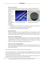
Figure 1: Membrane Tube Diffusor
Figure 2: Membrane Plate Diffusor
KLARO GmbH
Original Operating Manual for KLARO Small Wastewater Treatment Plant V.15.07
13
The KLplus/KL24plus controller can operate the plant depending on the actual wastewater inflow.
Prerequisite is the activation of level monitor by a professional.
Important:
All chambers/tanks must be vented. This is usually achieved through the drains, which are
vented through the roof. If necessary, additional air ducts or vents must be installed. The ventilation
ducts must be installed in a manner that allows for natural ventilation (chimney effect).
4.2. Systems with Additional Nitrogen Removal (Process Classes N and D)
The nitrogen removal is also carried out biologically with the help of specific strains of microorganisms.
Plants with additional nitrification use intensive aeration to create particularly suitable living conditions for
nitrifying bacteria, which convert ammonium into nitrate. For systems that are designed for additional
denitrification, short aeration bursts at the beginning of the aeration phase cause circulation of the water
and stimulate the denitrifying bacteria, which convert nitrates into elemental nitrogen.
4.3. Systems with Additional Phosphate Elimination (Process Class +P)
The phosphate precipitation takes place by addition of poly-aluminium chloride to the SBR reactor. The
phosphate precipitation system includes a removable holding platform in the dome part or on the partition
wall of the tank. The precipitant canister is installed on this platform. The control cabinet of the plant
contains a metering pump. It sucks the precipitant from the precipitant canister and releases it into the
SBR reactor. The addition of the precipitant takes place during the aeration phase of the reactor. The
required precipitant can be adjusted via the dosing pump. During the aeration phase, mixing takes place.
The precipitant creates an insoluble compound with the phosphate, which settles well in the tank.
The commissioning and operation of the dosing pump is described under point 6.2.4.
4.4. Systems with Additional Sanitation (Process Class +S)
The optional KLARO UV module is used for sanitation of biologically treated wastewater. Sanitation is
achieved by means of ultraviolet light (UV). It is an effective, economical, and particularly environmentally
friendly process. UV light kills pathogenic microorganisms within seconds without leaving any residue,
harmful by-products, or odours. The UV-light effect is utilised through the application of particularly
effective UVC radiation (254 nm). Within a few seconds, it causes a photochemical reaction in the DNA
(deoxyribonucleic acid), which is vital for all microorganisms. Thus, the microorganism is either killed or
its reproducibility is disabled.
The UV irradiation results in no undesired side reactions at the UV dose levels used for the sterilisation.
Since no disinfecting active substance is added to the water by the UV radiation, no deposit effects are
present after passing through the UV reactor.
5.
Control of the Small Wastewater Treatment Plant
The system is operated via the controller in the cabinet door (or inside the cabinet for outdoor cabinets).
It allows setting the operating parameters, displaying operating statuses, and querying system
parameters, as well as programming of operating hours by a specialist company.
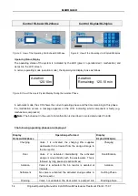
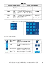
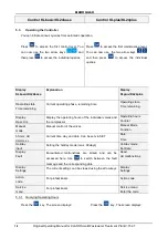
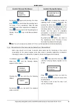
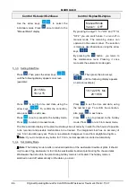
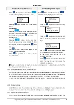
The contrast of the display can be changed in automatic mode by simultaneously pressing ESC and the
arrow keys.
The following figures show the structure of the operating units.
KLARO GmbH
2
Original Operating Manual for KLARO Small Wastewater Treatment Plant V.15.07
IMPORTANT:
•
This Operating Manual contains information about the plant, from installation
to maintenance, and must therefore be read before commissioning of the
plant!
•
All safety instructions must be observed!
•
The Operating Manual must be kept readily available during the operation of
the plant!
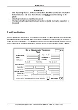
Plant Specifications
For any questions in the course of the operation of the plant, the specifications of your plant should
be noted as follows. With the help of this information, our staff will be able to help you more quickly
in the event of a malfunction. The specifications can be found on the nameplate, which is located
on the outside of the cabinet door for indoor cabinets, and inside the cabinet for outdoor cabinets.
Small Wastewater Treatment
Plant
PT
Sludge storage
Buffer
SB-Reactor
Approval No.:
Process class:
Certified:
Cabinet:
Controller:
Compressor:
Denomination:
Serial No.:
Article No.:
Additional module:
Article No.:
El. Connected load:
KLARO GmbH
Original Operating Manual for KLARO Small Wastewater Treatment Plant V.15.07
3
CONTENTS
Page
1.
About this Operating Manual
6
1.1.
Original Language of Documentation
6
1.2.
Completeness
6
1.3.
Liability
7
2.
Safety
7
2.1.
Explanation of Warnings and Prohibitions
7
2.2.
Hazard statements
8
2.3.
Warnings
9
2.4.
Exclusion for Use
10
3.
Warranty
10
4.
Function of the SBR Plant
10
4.1.
Plants for carbon elimination (process classes C)
11
4.2.
Systems with Additional Nitrogen Removal (Process Classes N and D)
13
4.3.
Systems with Additional Phosphate Elimination (Process Class +P)
13
4.4.
Systems with Additional Sanitation (Process Class +S)
13
5.
Control of the Small Wastewater Treatment Plant
13
5.1.
Connections to the KL-controls (230V option for solenoid valves)
16
5.2.
Connections to the KL24 controller(24V option for stepper motor valves)
16
5.3.
Operating the Controller
18
5.3.1.
Querying Operating Hours
18
5.3.2.
Manual Control of the Valves and the Cabinet Fan in "Manual Mode"
19
5.3.3.
Setting Date/Time
20
5.3.4.
Set Holiday Mode
20
5.3.5.
Query Malfunctions - Query Old Malfunctions
21
5.3.6.
Display Settings
21
5.3.7.
Service Menu and Action Code
21
5.4.
Changing the Fuses
22
5.5.
Operation of Power Failure Detector
22
6.
Additional functions of the Controllers KLplus/ KL24plus and KLbasic/KL24base
23
6.1.
Underload detection (KLplus/KL24plus)
23
6.1.1.
Mode of Operation
24
6.1.2.
Commissioning
24
6.1.3.
Switching Off the Level Measurement
25
6.1.4.
Safety and Fault Messages
25
6.2.
Optional Functions
26
6.2.1.
Connection of an external alarm device
26
6.2.2.
Connection of a contactor for switching the compressor
26
6.2.3.
Connection of a UV reactor
26
6.2.4.
Phosphate precipitation with metering pump
26
7.
Maintenance, Repair and Operation
28
7.1.
Sludge Evacuation
28
7.2.
Operating Instructions
29
8.
Fault Messages and Troubleshooting
31
8.1.
Fault Message on the Display
32
8.2.
Unusual Water Levels - Troubleshooting
33
KLARO GmbH
2
Original Operating Manual for KLARO Small Wastewater Treatment Plant V.15.07
IMPORTANT:
•
This Operating Manual contains information about the plant, from installation
to maintenance, and must therefore be read before commissioning of the
plant!
•
All safety instructions must be observed!
•
The Operating Manual must be kept readily available during the operation of
the plant!
Plant Specifications
For any questions in the course of the operation of the plant, the specifications of your plant should
be noted as follows. With the help of this information, our staff will be able to help you more quickly
in the event of a malfunction. The specifications can be found on the nameplate, which is located
on the outside of the cabinet door for indoor cabinets, and inside the cabinet for outdoor cabinets.
Small Wastewater Treatment
Plant
PT
Sludge storage
Buffer
SB-Reactor
Approval No.:
Process class:
Certified:
Cabinet:
Controller:
Compressor:
Denomination:
Serial No.:
Article No.:
Additional module:
Article No.:
El. Connected load:
KLARO GmbH
Original Operating Manual for KLARO Small Wastewater Treatment Plant V.15.07
3
CONTENTS
Page
1.
About this Operating Manual
6
1.1.
Original Language of Documentation
6
1.2.
Completeness
6
1.3.
Liability
7
2.
Safety
7
2.1.
Explanation of Warnings and Prohibitions
7
2.2.
Hazard statements
8
2.3.
Warnings
9
2.4.
Exclusion for Use
10
3.
Warranty
10
4.
Function of the SBR Plant
10
4.1.
Plants for carbon elimination (process classes C)
11
4.2.
Systems with Additional Nitrogen Removal (Process Classes N and D)
13
4.3.
Systems with Additional Phosphate Elimination (Process Class +P)
13
4.4.
Systems with Additional Sanitation (Process Class +S)
13
5.
Control of the Small Wastewater Treatment Plant
13
5.1.
Connections to the KL-controls (230V option for solenoid valves)
16
5.2.
Connections to the KL24 controller(24V option for stepper motor valves)
16
5.3.
Operating the Controller
18
5.3.1.
Querying Operating Hours
18
5.3.2.
Manual Control of the Valves and the Cabinet Fan in "Manual Mode"
19
5.3.3.
Setting Date/Time
20
5.3.4.
Set Holiday Mode
20
5.3.5.
Query Malfunctions - Query Old Malfunctions
21
5.3.6.
Display Settings
21
5.3.7.
Service Menu and Action Code
21
5.4.
Changing the Fuses
22
5.5.
Operation of Power Failure Detector
22
6.
Additional functions of the Controllers KLplus/ KL24plus and KLbasic/KL24base
23
6.1.
Underload detection (KLplus/KL24plus)
23
6.1.1.
Mode of Operation
24
6.1.2.
Commissioning
24
6.1.3.
Switching Off the Level Measurement
25
6.1.4.
Safety and Fault Messages
25
6.2.
Optional Functions
26
6.2.1.
Connection of an external alarm device
26
6.2.2.
Connection of a contactor for switching the compressor
26
6.2.3.
Connection of a UV reactor
26
6.2.4.
Phosphate precipitation with metering pump
26
7.
Maintenance, Repair and Operation
28
7.1.
Sludge Evacuation
28
7.2.
Operating Instructions
29
8.
Fault Messages and Troubleshooting
31
8.1.
Fault Message on the Display
32
8.2.
Unusual Water Levels - Troubleshooting
33
13


