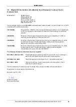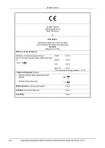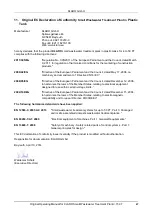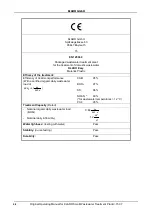
KLARO GmbH
50
Original Operating Manual for KLARO Small Wastewater Treatment Plant V.15.07
13.
Plant Datasheets
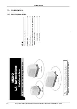
13.1. Piston Compressor Nitto
KLARO GmbH
Original Operating Manual for KLARO Small Wastewater Treatment Plant V.15.07
51
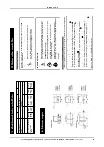
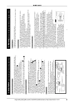
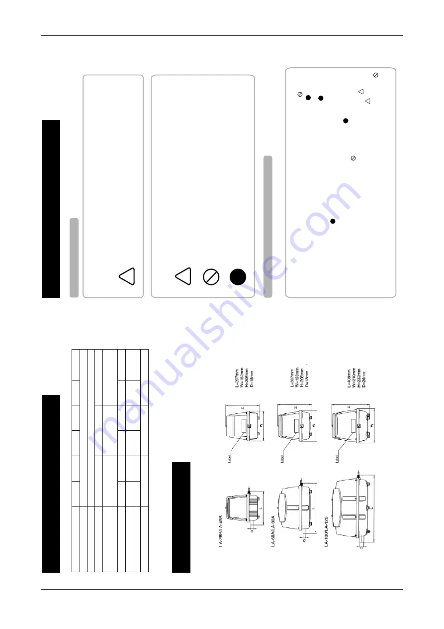
1. Modelle und tec
hnische Daten
2. Abmessungen
Model
LA-28B LA-45B LA-60A
LA-80A
LA-100 LA-120
Betriebsspa
nnung
120V A
C OR 230V AC
Frequ
enz
50Hz/60Hz
Betriebsdruc
k
110mbar(0.11Kgf/cm2) 150mbar(0.15kgf/cm2) 180mbar(0.18kgf/cm2)
Einsatzdruckbereich
50-200mbar
50-200mbar
50-250mbar
(0.05-0.2kgf/cm2) (0.05-0.2kgf/cm2)
(0.05-0.25kgf/cm2)
Luftförderr
ate bei Betriebsdruck
28l/min
45l/min 60l/min 80l/min
100l/min 120l/min
Energieaufnahme
29/26W 47/45W 64/60W 86/80W 100/95W
130/118W
Gewicht
2,9 Kg 3,0 Kg
5,0 Kg
5,3 Kg
9,4 Kg 9,4 Kg
Abmessungen L/B/H
207mm/182mm/205mm 307mm/190mm/208mm 408mm/210mm/232mm
-2-
AD
AD
AD
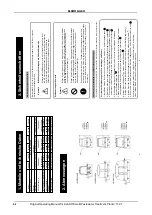
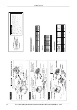
3. Sic
herheitsvor
schriften
Erklärung der grafischen Symbole
Sicherheitsvorschriften/hinweise und Bedienungsanweisungen
Zur Unfallverhütung und elektrischen Sicherheit sollten folgende Sicherheitsmaßnahmen immer bef
olgt werden.
-3-
Der Ausdruck “V
orsicht”, welcher in dieser Anleitung verwendet wird, soll Sie auf folgende
Gefahren aufmerksam machen.
Die Bedeutung der Symbole
Vor
sicht zur V
erhinderung eines Stromschlages und Feuers
Dieser Ausdruck/dieses Symbol weist auf die Möglichkeit hin, dass
die Mißachtung des Ausdrucks “V
orsicht”, also das weiterarbeiten
bzw.
die falsche Anwendung ohne völliges V
erständnis zu
körperlichen Verletzungen oder Schädigungen führen kann.
Dieses Symbol weist auf einen Gegenstand hin, welcher beachtet werden
sollte (inclusive W
arnung und Gefahr). Die wichtigsten Hinweise w
erden
durch ein Bild, ein Wort, oder einen erklärenden T
ext innerhalb oder
entlang des Symbols aufgezeigt.
Dieses Symbol weist auf einen Gegenstand hin, welcher beachtet werden
sollte (inclusive W
arnung und Gefahr). Die wichtigsten Hinweise w
erden
durch ein Bild, ein Wort, oder einen erklärenden T
ext innerhalb oder
entlang des Symbols aufgezeigt.
Dieses Symbol weist auf eine Tätigkeit hin w
elche zwingend ausgeführt
werden muss, um eine Gefahr zu vermeiden.
Die wichtigsten Hinweise werden
durch ein Bild oder ein erklärenden T
ext innerhalb oder entlang des Symbols
aufgezeigt.
1. Installieren Sie den Belüfter nicht an einer Stelle an welcher er überflutet werden kann.
2. Elektrische Arbeiten müssen von einem qualifizierten Elektriker durchgeführt werden.
3. Die Stromversorgung sollte der
, auf dem Etikett des Belüfters, vorgegebenen Spannung
entsprechen und mit einer Erdung sowie einem Überspannungsschutz montiert sein.
4. Die benutzte Steckdose sollte w
asserdicht sein sowie eine entsprechende V
erbindung
mit einer Erdung aufweisen.
5.
Wenn das Kabel beschädigt ist muss es durch den Hersteller, seine autorisierten Händler
oder qualifizierte Personen ersetzt werden, um eine Gefahr zu vermeiden.
6. Stellen Sie keine Gegenstände auf das elektrische Kabel.
7. Stellen Sie sicher
, dass der Belüfter ausgesteckt ist bevor Sie mit der
Wartung beginnen.
8. Stellen Sie sicher
, dass der Gehäusedeckel nach der W
artung wieder montiert wird.
9.
Berühren Sie nicht die Metallteile des Belüfters bis er abgekühlt ist, da der Belüfter sehr heiss läuft.
Die Nichtbeachtung einer der oben aufgeführten Punkte könnte einen Stromschlag, einen offenen Brand oder einen Schwelbrand verursachen.
Bitte beachten Sie dringend die Sicherheitshinweise
Ausdruck
Symbole
!
!
!
!
!
!
!
!
!
ö
ä
ö
ü
ö
ö ä
ä
ä
ä
ä
ä
ü
ü
ü
ü
ü
ü
Ü
ä
ä
ü
ü
ü
ö
ü
ü
ä
ü
ä
ä
ß
KLARO GmbH
2
Original Operating Manual for KLARO Small Wastewater Treatment Plant V.15.07
IMPORTANT:
•
This Operating Manual contains information about the plant, from installation
to maintenance, and must therefore be read before commissioning of the
plant!
•
All safety instructions must be observed!
•
The Operating Manual must be kept readily available during the operation of
the plant!
Plant Specifications
For any questions in the course of the operation of the plant, the specifications of your plant should
be noted as follows. With the help of this information, our staff will be able to help you more quickly
in the event of a malfunction. The specifications can be found on the nameplate, which is located
on the outside of the cabinet door for indoor cabinets, and inside the cabinet for outdoor cabinets.
Small Wastewater Treatment
Plant
PT
Sludge storage
Buffer
SB-Reactor
Approval No.:
Process class:
Certified:
Cabinet:
Controller:
Compressor:
Denomination:
Serial No.:
Article No.:
Additional module:
Article No.:
El. Connected load:
KLARO GmbH
Original Operating Manual for KLARO Small Wastewater Treatment Plant V.15.07
3
CONTENTS
Page
1.
About this Operating Manual
6
1.1.
Original Language of Documentation
6
1.2.
Completeness
6
1.3.
Liability
7
2.
Safety
7
2.1.
Explanation of Warnings and Prohibitions
7
2.2.
Hazard statements
8
2.3.
Warnings
9
2.4.
Exclusion for Use
10
3.
Warranty
10
4.
Function of the SBR Plant
10
4.1.
Plants for carbon elimination (process classes C)
11
4.2.
Systems with Additional Nitrogen Removal (Process Classes N and D)
13
4.3.
Systems with Additional Phosphate Elimination (Process Class +P)
13
4.4.
Systems with Additional Sanitation (Process Class +S)
13
5.
Control of the Small Wastewater Treatment Plant
13
5.1.
Connections to the KL-controls (230V option for solenoid valves)
16
5.2.
Connections to the KL24 controller(24V option for stepper motor valves)
16
5.3.
Operating the Controller
18
5.3.1.
Querying Operating Hours
18
5.3.2.
Manual Control of the Valves and the Cabinet Fan in "Manual Mode"
19
5.3.3.
Setting Date/Time
20
5.3.4.
Set Holiday Mode
20
5.3.5.
Query Malfunctions - Query Old Malfunctions
21
5.3.6.
Display Settings
21
5.3.7.
Service Menu and Action Code
21
5.4.
Changing the Fuses
22
5.5.
Operation of Power Failure Detector
22
6.
Additional functions of the Controllers KLplus/ KL24plus and KLbasic/KL24base
23
6.1.
Underload detection (KLplus/KL24plus)
23
6.1.1.
Mode of Operation
24
6.1.2.
Commissioning
24
6.1.3.
Switching Off the Level Measurement
25
6.1.4.
Safety and Fault Messages
25
6.2.
Optional Functions
26
6.2.1.
Connection of an external alarm device
26
6.2.2.
Connection of a contactor for switching the compressor
26
6.2.3.
Connection of a UV reactor
26
6.2.4.
Phosphate precipitation with metering pump
26
7.
Maintenance, Repair and Operation
28
7.1.
Sludge Evacuation
28
7.2.
Operating Instructions
29
8.
Fault Messages and Troubleshooting
31
8.1.
Fault Message on the Display
32
8.2.
Unusual Water Levels - Troubleshooting
33
KLARO GmbH
2
Original Operating Manual for KLARO Small Wastewater Treatment Plant V.15.07
IMPORTANT:
•
This Operating Manual contains information about the plant, from installation
to maintenance, and must therefore be read before commissioning of the
plant!
•
All safety instructions must be observed!
•
The Operating Manual must be kept readily available during the operation of
the plant!
Plant Specifications
For any questions in the course of the operation of the plant, the specifications of your plant should
be noted as follows. With the help of this information, our staff will be able to help you more quickly
in the event of a malfunction. The specifications can be found on the nameplate, which is located
on the outside of the cabinet door for indoor cabinets, and inside the cabinet for outdoor cabinets.
Small Wastewater Treatment
Plant
PT
Sludge storage
Buffer
SB-Reactor
Approval No.:
Process class:
Certified:
Cabinet:
Controller:
Compressor:
Denomination:
Serial No.:
Article No.:
Additional module:
Article No.:
El. Connected load:
KLARO GmbH
Original Operating Manual for KLARO Small Wastewater Treatment Plant V.15.07
3
CONTENTS
Page
1.
About this Operating Manual
6
1.1.
Original Language of Documentation
6
1.2.
Completeness
6
1.3.
Liability
7
2.
Safety
7
2.1.
Explanation of Warnings and Prohibitions
7
2.2.
Hazard statements
8
2.3.
Warnings
9
2.4.
Exclusion for Use
10
3.
Warranty
10
4.
Function of the SBR Plant
10
4.1.
Plants for carbon elimination (process classes C)
11
4.2.
Systems with Additional Nitrogen Removal (Process Classes N and D)
13
4.3.
Systems with Additional Phosphate Elimination (Process Class +P)
13
4.4.
Systems with Additional Sanitation (Process Class +S)
13
5.
Control of the Small Wastewater Treatment Plant
13
5.1.
Connections to the KL-controls (230V option for solenoid valves)
16
5.2.
Connections to the KL24 controller(24V option for stepper motor valves)
16
5.3.
Operating the Controller
18
5.3.1.
Querying Operating Hours
18
5.3.2.
Manual Control of the Valves and the Cabinet Fan in "Manual Mode"
19
5.3.3.
Setting Date/Time
20
5.3.4.
Set Holiday Mode
20
5.3.5.
Query Malfunctions - Query Old Malfunctions
21
5.3.6.
Display Settings
21
5.3.7.
Service Menu and Action Code
21
5.4.
Changing the Fuses
22
5.5.
Operation of Power Failure Detector
22
6.
Additional functions of the Controllers KLplus/ KL24plus and KLbasic/KL24base
23
6.1.
Underload detection (KLplus/KL24plus)
23
6.1.1.
Mode of Operation
24
6.1.2.
Commissioning
24
6.1.3.
Switching Off the Level Measurement
25
6.1.4.
Safety and Fault Messages
25
6.2.
Optional Functions
26
6.2.1.
Connection of an external alarm device
26
6.2.2.
Connection of a contactor for switching the compressor
26
6.2.3.
Connection of a UV reactor
26
6.2.4.
Phosphate precipitation with metering pump
26
7.
Maintenance, Repair and Operation
28
7.1.
Sludge Evacuation
28
7.2.
Operating Instructions
29
8.
Fault Messages and Troubleshooting
31
8.1.
Fault Message on the Display
32
8.2.
Unusual Water Levels - Troubleshooting
33
51

