KLARO GmbH
28
Original Operating Manual for KLARO Small Wastewater Treatment Plant V.15.07
Reference Values for Setting
the Pump Capacity
P
[ml/min]
1
1.5
2
5.5
3
11.0
4
15.0
5
19.0
6
22.5
7
26.0
8
30.5
9
35.0
10
37.5
DP12 DP24
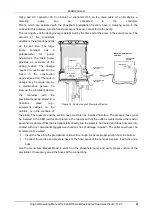
Figure 13: Dosing Pump Compact
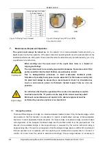
Figure 14: Dosing Pump DP12 and DP24
Flow rate: 5.5 ml/min
7.
Maintenance, Repair and Operation
The system must always be turned on.
As the operator of a small wastewater treatment plant, you
must
ensure trouble-free operation of the plant. Almost all operating faults result in a deterioration of the
treatment performance of the plant. These must therefore be detected early and eliminated by you or by
a qualified service technician.
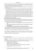
Fall Hazard
When working near the open cover of the septic tank, there is a hazard of
tripping and falling!
The open tank must be secured by appropriate measures. Operators and/or third
parties could fall into the tank! Children are particularly at risk!
Due to biodegradation processes in small wastewater treatment plants,
formation of (possibly toxic) gases can be expected. For this reason an entry into
the plant must always be secured by a second person. Under no circumstances
must an unconscious person be followed. Instead request help as soon as
possible.
High Voltage
For activities other than the operation of the control, the maintenance switch
must be turned to the "0" position or the plug of the cabinet must be pulled!
Work such as maintenance and repairs to the cabinet equipment must be
performed by a service engineer or an electrician!
7.1. Sludge Evacuation
There are different types of sludge in a small wastewater treatment plant. Only the faecal sludge, which
accumulates in the first chamber, is evacuated. It consists of sedimented residues of the wastewater
treatment. In small wastewater treatment plants, the faecal sludge or treatment sludge consists of dead
microorganisms of the biological treatment stage and the settled solids from the pre-treatment. The
amount of accumulated sludge in the sludge storage is measured by the service technician using a
sludge lancing lifter. The system is designed so that the sludge storage space is sufficient for permanent
full-load operation and compliance with the operating and maintenance requirements for at least 12
months. At a lower load, this period is extended accordingly. Timely sludge disposal is necessary to
KLARO GmbH
Original Operating Manual for KLARO Small Wastewater Treatment Plant V.15.07
29
prevent the overflowing of the solids into the biological stage with an increasing amount of sludge
produced. Sludge regulation and sanitation are important prerequisites for good treatment performance
and a long service life of the small wastewater treatment plant.
The regulations for sludge disposal are set by the municipalities. Sludge removal is required either
regularly or as needed:
-
The regular sludge removal takes place on specific dates and is determined by the municipalities at
1-2 times per year, depending on the plant type, size of the chambers, and connected residents.
-
Needs-based sludge removal is flexible and takes place at shorter or longer intervals. In this case,
the maintenance technician checks the sludge level (sludge level measurement) and informs the
responsible waste disposal company of the date of the required sludge disposal. The sludge
disposal must be done no later than at 70% fill level of the sludge storage. In some cases, the
maintenance technician will inform the operator and the operator will arrange a date for disposal.
If maintenance and sludge removal happen to take place at the same time, the sludge removal must be
done after the maintenance. The sludge removal must be recorded in the log book. Please also refer to
the instructions of your specialist company.
The following points must be observed for sludge removal:
As a rule, only the pre-treatment chamber of the small wastewater treatment plant must be emptied. In
case of improper sludge regulation of the plant, pumping of the lower portion of the secondary treatment
chamber or the superficial pumping of scum might be necessary.
First
the scum is pumped from the surface,
then
the suction tube is placed on the bottom of the
tank.
At the bottom, a residual amount of water of about 10 cm should remain in the pre-
treatment chamber.
After emptying the pre-treatment chamber must be refilled with fresh water!
Complete emptying of the septic system is useful only if a malfunction is present, the cause of which
cannot be determined, or if repair work beneath the water's edge on the inside of the tank is required.
The necessity of such a complete emptying is best decided by the maintenance specialist.
As the operator of a small wastewater treatment plant, ensure that the right chamber of the plant is
pumped out. Excessive pumping of sludge may interfere with the operation of the small wastewater
treatment plant and causes unnecessary expenses!
7.2. Operating Instructions
As a rule, only substances should be fed to the plant that meet the characteristics of domestic
wastewater.
Biocides, toxic or biologically incompatible or non-degradable substances must not enter the plant as
they result in biological process problems. In particular, the following may not enter the plant:
-
Rainwater from roofs and courtyards,
-
Extraneous water (e.g., drainage water)
-
Residues from livestock in solid and liquid form,
-
Commercial or agricultural wastewater, if it is not comparable to domestic wastewater,
-
Chemicals, pharmaceuticals, mineral oils, solvents,
-
Cooling water,
KLARO GmbH
2
Original Operating Manual for KLARO Small Wastewater Treatment Plant V.15.07
IMPORTANT:
•
This Operating Manual contains information about the plant, from installation
to maintenance, and must therefore be read before commissioning of the
plant!
•
All safety instructions must be observed!
•
The Operating Manual must be kept readily available during the operation of
the plant!
Plant Specifications
For any questions in the course of the operation of the plant, the specifications of your plant should
be noted as follows. With the help of this information, our staff will be able to help you more quickly
in the event of a malfunction. The specifications can be found on the nameplate, which is located
on the outside of the cabinet door for indoor cabinets, and inside the cabinet for outdoor cabinets.
Small Wastewater Treatment
Plant
PT
Sludge storage
Buffer
SB-Reactor
Approval No.:
Process class:
Certified:
Cabinet:
Controller:
Compressor:
Denomination:
Serial No.:
Article No.:
Additional module:
Article No.:
El. Connected load:
KLARO GmbH
Original Operating Manual for KLARO Small Wastewater Treatment Plant V.15.07
3
CONTENTS
Page
1.
About this Operating Manual
6
1.1.
Original Language of Documentation
6
1.2.
Completeness
6
1.3.
Liability
7
2.
Safety
7
2.1.
Explanation of Warnings and Prohibitions
7
2.2.
Hazard statements
8
2.3.
Warnings
9
2.4.
Exclusion for Use
10
3.
Warranty
10
4.
Function of the SBR Plant
10
4.1.
Plants for carbon elimination (process classes C)
11
4.2.
Systems with Additional Nitrogen Removal (Process Classes N and D)
13
4.3.
Systems with Additional Phosphate Elimination (Process Class +P)
13
4.4.
Systems with Additional Sanitation (Process Class +S)
13
5.
Control of the Small Wastewater Treatment Plant
13
5.1.
Connections to the KL-controls (230V option for solenoid valves)
16
5.2.
Connections to the KL24 controller(24V option for stepper motor valves)
16
5.3.
Operating the Controller
18
5.3.1.
Querying Operating Hours
18
5.3.2.
Manual Control of the Valves and the Cabinet Fan in "Manual Mode"
19
5.3.3.
Setting Date/Time
20
5.3.4.
Set Holiday Mode
20
5.3.5.
Query Malfunctions - Query Old Malfunctions
21
5.3.6.
Display Settings
21
5.3.7.
Service Menu and Action Code
21
5.4.
Changing the Fuses
22
5.5.
Operation of Power Failure Detector
22
6.
Additional functions of the Controllers KLplus/ KL24plus and KLbasic/KL24base
23
6.1.
Underload detection (KLplus/KL24plus)
23
6.1.1.
Mode of Operation
24
6.1.2.
Commissioning
24
6.1.3.
Switching Off the Level Measurement
25
6.1.4.
Safety and Fault Messages
25
6.2.
Optional Functions
26
6.2.1.
Connection of an external alarm device
26
6.2.2.
Connection of a contactor for switching the compressor
26
6.2.3.
Connection of a UV reactor
26
6.2.4.
Phosphate precipitation with metering pump
26
7.
Maintenance, Repair and Operation
28
7.1.
Sludge Evacuation
28
7.2.
Operating Instructions
29
8.
Fault Messages and Troubleshooting
31
8.1.
Fault Message on the Display
32
8.2.
Unusual Water Levels - Troubleshooting
33
KLARO GmbH
2
Original Operating Manual for KLARO Small Wastewater Treatment Plant V.15.07
IMPORTANT:
•
This Operating Manual contains information about the plant, from installation
to maintenance, and must therefore be read before commissioning of the
plant!
•
All safety instructions must be observed!
•
The Operating Manual must be kept readily available during the operation of
the plant!
Plant Specifications
For any questions in the course of the operation of the plant, the specifications of your plant should
be noted as follows. With the help of this information, our staff will be able to help you more quickly
in the event of a malfunction. The specifications can be found on the nameplate, which is located
on the outside of the cabinet door for indoor cabinets, and inside the cabinet for outdoor cabinets.
Small Wastewater Treatment
Plant
PT
Sludge storage
Buffer
SB-Reactor
Approval No.:
Process class:
Certified:
Cabinet:
Controller:
Compressor:
Denomination:
Serial No.:
Article No.:
Additional module:
Article No.:
El. Connected load:
KLARO GmbH
Original Operating Manual for KLARO Small Wastewater Treatment Plant V.15.07
3
CONTENTS
Page
1.
About this Operating Manual
6
1.1.
Original Language of Documentation
6
1.2.
Completeness
6
1.3.
Liability
7
2.
Safety
7
2.1.
Explanation of Warnings and Prohibitions
7
2.2.
Hazard statements
8
2.3.
Warnings
9
2.4.
Exclusion for Use
10
3.
Warranty
10
4.
Function of the SBR Plant
10
4.1.
Plants for carbon elimination (process classes C)
11
4.2.
Systems with Additional Nitrogen Removal (Process Classes N and D)
13
4.3.
Systems with Additional Phosphate Elimination (Process Class +P)
13
4.4.
Systems with Additional Sanitation (Process Class +S)
13
5.
Control of the Small Wastewater Treatment Plant
13
5.1.
Connections to the KL-controls (230V option for solenoid valves)
16
5.2.
Connections to the KL24 controller(24V option for stepper motor valves)
16
5.3.
Operating the Controller
18
5.3.1.
Querying Operating Hours
18
5.3.2.
Manual Control of the Valves and the Cabinet Fan in "Manual Mode"
19
5.3.3.
Setting Date/Time
20
5.3.4.
Set Holiday Mode
20
5.3.5.
Query Malfunctions - Query Old Malfunctions
21
5.3.6.
Display Settings
21
5.3.7.
Service Menu and Action Code
21
5.4.
Changing the Fuses
22
5.5.
Operation of Power Failure Detector
22
6.
Additional functions of the Controllers KLplus/ KL24plus and KLbasic/KL24base
23
6.1.
Underload detection (KLplus/KL24plus)
23
6.1.1.
Mode of Operation
24
6.1.2.
Commissioning
24
6.1.3.
Switching Off the Level Measurement
25
6.1.4.
Safety and Fault Messages
25
6.2.
Optional Functions
26
6.2.1.
Connection of an external alarm device
26
6.2.2.
Connection of a contactor for switching the compressor
26
6.2.3.
Connection of a UV reactor
26
6.2.4.
Phosphate precipitation with metering pump
26
7.
Maintenance, Repair and Operation
28
7.1.
Sludge Evacuation
28
7.2.
Operating Instructions
29
8.
Fault Messages and Troubleshooting
31
8.1.
Fault Message on the Display
32
8.2.
Unusual Water Levels - Troubleshooting
33
29

