background image

4-8

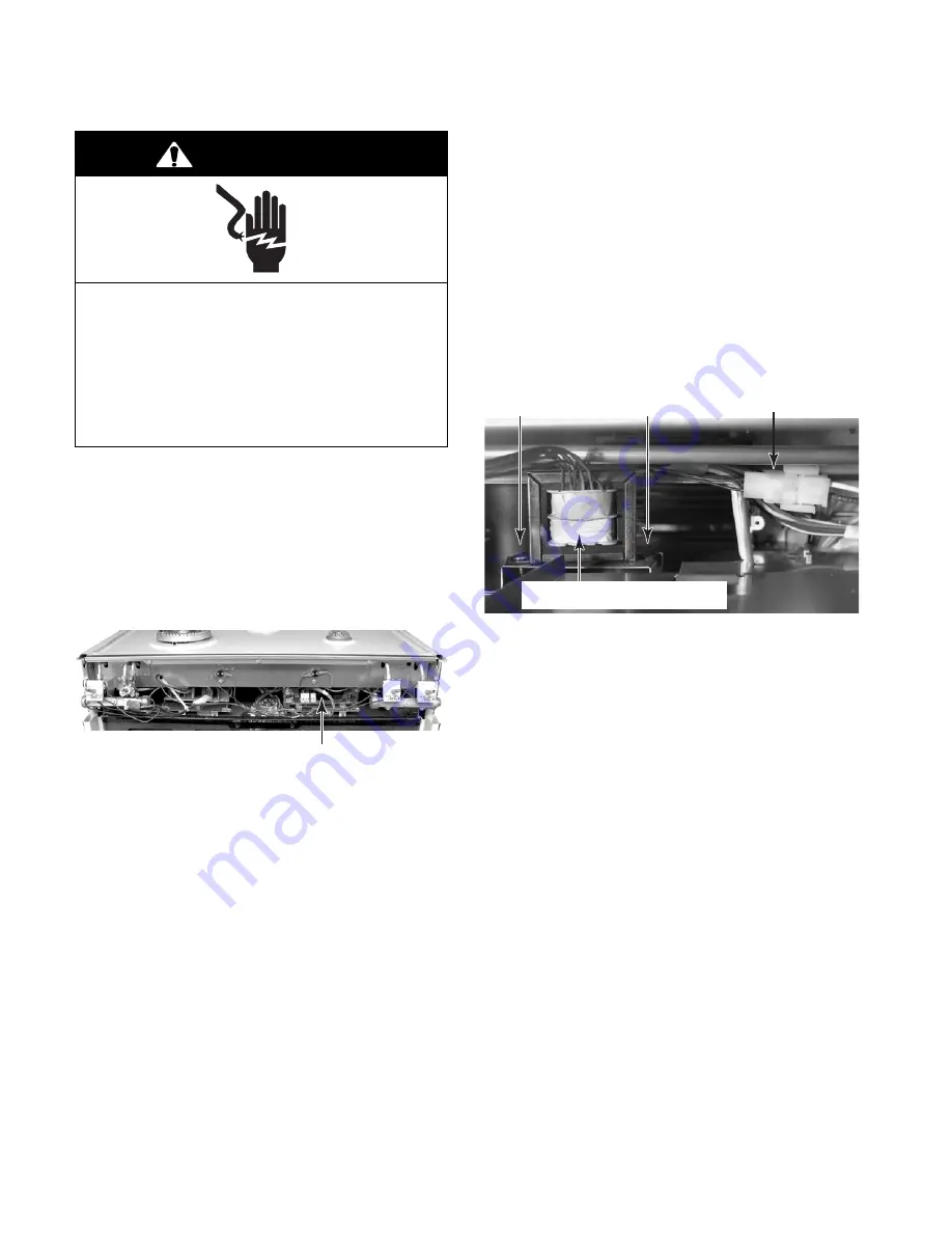
REMOVING THE POWER SUPPLY TRANSFORMER

1.

Unplug range or disconnect power.

2.

Turn off gas supply to range.

3.

Remove the control panel (see step 4 on
page 4-2 for the procedure).

4.

Remove  the  control  power  supply  (see
step 7 on page 4-7 for the procedure).

Electrical Shock Hazard

Disconnect power before servicing.

Replace all parts and panels before
operating.

Failure to do so can result in death or
electrical shock.

WARNING

5.

Using  a  90

°

  offset  screwdriver,  remove

the  screw  from  the  power  supply  trans-
former.

6.

Disconnect the 2-wire primary wire con-
nector  on  the  power  supply  transformer
from the wiring harness. Cut the wire tie
from around the primary wires.

7.

Unhook the flange on the end of the power
supply  transformer  from  the  mounting
bracket slot, and remove the transformer
from the front of the unit.

Power Supply Transformer

(Behind Control Power Supply)

Screw

Power Supply Transformer

Flange  In Slot

Primary Connector

Summary of Contents for KGRA806P

Page 1: ...TECHNICAL EDUCATION JOB AID 4317367 KAC 42 SELF CLEANING SLIDE IN FREESTANDING GAS RANGES Freestanding Models KGRA806P KGRI801P Slide In Models KGSA906P KGSI901P ...

Page 2: ...ith the gas range The Wiring Diagrams and Strip Circuits used in this Job Aid are typical and should be used for training purposes only Always use the Wiring Diagram supplied with the product when servicing the unit GOALS AND OBJECTIVES The goal of this Job Aid is to provide detailed information that will enable the service technician to properly diagnose malfunctions and repair KitchenAid Self Cl...

Page 3: ...ntrol Cooling Fan Thermal Switches 4 4 Removing The Door Latch Assembly The Spark Module DSI And The Control Power Supply 4 6 Removing The Power Supply Transformer 4 8 Removing The Cooktop And A Surface Burner Ignitor 4 9 Removing The Rear Panel 4 12 Removing An Oven Light Socket Assembly 4 13 Removing The Broil Burner Ignitor Halo Broil Element 4 14 Removing The Bake Burner And Ignitor 4 16 Remov...

Page 4: ...ransformer 5 4 Halo Broil Element 5 4 Convection Element 5 5 Convection Fan Motor 5 5 Oven Temperature Sensor 5 6 Cooling Fan Motor 5 6 Oven TOD 5 7 Gas Distribution Valve 5 7 Clock Models KGRA806P KGSA906P 5 8 Clock Models KGRI801P KGSI901P 5 11 DIAGNOSTICS TROUBLESHOOTING 6 1 Diagnostics 6 1 Troubleshooting 6 6 WIRING DIAGRAMS STRIP CIRCUITS 7 1 Wiring Diagrams 7 1 Strip Circuits 7 3 ...

Page 5: ...kill or hurt you and others All safety messages will follow the safety alert symbol and either the word DANGER or WARNING These words mean DANGER WARNING All safety messages will tell you what the potential hazard is tell you how to reduce the chance of injury and tell you what can happen if the instructions are not followed You can be killed or seriously injured if you don t immediately follow in...

Page 6: ...IDE 9 SLIDE IN FEATURES 0 CONVENTIONAL OVEN COIL COOKTOP 1 CONVENTIONAL OVEN CERAN OR GAS COOKTOP 2 CONVENTIONAL OVEN WARMING DRAWER GAS COOKTOP 3 CONVENTIONAL OVEN AUTO CONVECT CERAN OR GAS COOKTOP 4 CONVECTION OVEN COIL COOKTOP 5 CONVECTION OVEN CERAN COOKTOP 6 CONVECTION OVEN GAS COOKTOP W TRIPLE TIER 7 CONVECTION OVEN WARMING DRAWER CERAN COOKTOP W ELECTRONIC KNOB COOKTOP OR GAS COOKTOP W TRIP...

Page 7: ...MODEL SERIAL NUMBER LABEL TECH SHEET LOCATIONS The Model Serial Number label and Tech Sheet locations are shown below Model Serial Number Location On Chassis Frame Tech Sheet Location On Underside Of Drawer ...

Page 8: ... Standard Standard Cleaning System Self Cleaning Timed Self Cleaning Timed Auto Self Clean Latch Yes Motorized Yes Motorized Oven Volume cu ft Overall Capacity 3 8 AHAM Overall Capacity 3 8 AHAM Oven Ignition Type Electronic Electronic Gas Broiler Type Log Burner with 1200 W Halo Element Log Burner with 1200 W Halo Element Gas Bake Output BTU Nat LP 16500 BTU 16500 BTU 16500 BTU 16500 BTU Gas Broi...

Page 9: ...en Cooking System True Convection True Convection Cleaning System Self Cleaning Soil Level Timed Self Cleaning Soil Level Timed Auto Self Clean Latch Yes Motorized Yes Motorized Oven Volume cu ft Overall Capacity 3 6 AHAM Overall Capacity 3 6 AHAM Oven Ignition Type Electronic Electronic Gas Broiler Type Log Burner with 1200 W Halo Element Log Burner with 1200 W Halo Element Gas Bake Output BTU Na...

Page 10: ...erior Main Oven Cooking System True Convection Cleaning System Self Cleaning Soil Level Timed Auto Self Clean Latch Yes Motorized Oven Volume cu ft Overall Capacity 3 6 AHAM Oven Ignition Type Electronic Gas Broiler Type Log Burner with 1200 W Halo Element Gas Bake Output BTU Nat LP 16500 BTU 16500 BTU Gas Broil Output BTU Nat LP 10000 BTU 9000 BTU Oven Lower Panel Door Yes Accessories Griddle Yes...

Page 11: ... a different warranty may apply For details please contact your authorized KitchenAid dealer If you need service first see the Troubleshooting section of the Use and Care Guide After checking Trouble shooting additional help can be found by checking the Assistance or Service section or by calling our Customer Interaction Center telephone numbers listed below from anywhere in the U S A or Canada Ki...

Page 12: ...1 8 NOTES ...

Page 13: ...r each 1 000 feet 304 8 m above sea level Not applicable for Canada 3 This range is equipped for use with Natu ral gas It is design certified by AGA CSA for Natural and L P gas with appropriate conversion ConversiontoL P gascanbe made using the kit included in the litera turepackage Themodel serialratingplate has information on the type of gas that can be used If this information does not agree wi...

Page 14: ...fold pressure The inlet pressure to the regulator should be as follows for operation Natural gas Manifold pressure 5 inches Maximum pressure 14 inches L P gas Manifold pressure 10 inches Maximum pressure 14 inches 9 Line pressure testing Testing above 1 2 psi gauge The range and its individual shutoff valve must be disconnected from the gas supply piping system during any pressure testing of that ...

Page 15: ...checked by a qualified electrician to see if it is wired with correct polarity Copies of the standards listed may be obtained from National Fire Protection Association Batterymarch Park Quincy Massachusetts 02269 CSA International 8501 East Pleasant Valley Road Cleveland Ohio 44131 5575 NOTE The metal chassis of the range MUST be grounded in order for the control panel to work If the metal chassis...

Page 16: ...conversion from Natural to L P gas must be done by a qualified installer Examples of a qualified installer include licensed heating personnel authorized gas company personnel and authorized ser vice personnel L P gas must not be used unless the L P conversion has been made using the kit that is included with this range See the Gas Supply Requirements starting on page 2 1 Electrical Shock Hazard Di...

Page 17: ...from the burner cover and remove the cover Burner Cover Screw 1 of 3 d Remove the two T 20 torx screws from the orifice cover and remove the cover Orifice Cover 2 Screws e Use a 7 mm nut driver and remove the two burner orifices External Burner Orifice 4 Install the L P gas orifices in the burners as shown in the following charts do not overtighten them Rating Color Size Burner 5 000 B T U Red 0 7...

Page 18: ...ve for use with L P gas a Remove the storage drawer from the range Gas Distribution Valve 5 Place the natural gas orifices in the orifice card holes 6 Replace the burner caps and grates 7 To convert the broil burner for use with L P gas a Open the oven door and remove the oven racks b Use a 1 2 open end wrench and turn the orifice hood down snug onto the pin approximately 2 1 2 turns DO NOT OVERTI...

Page 19: ...l the plastic cap and the conver sion cap on the gas distribution valve with the L P side facing up you will see LP stamped inside the cap as shown below f Reinstall the storage drawer 10 Turn the gas supply valve handle on Conversion Cap Set For Use With L P Gas Plastic Cap Conversion Cap Set For Use With N Natural Gas L P Gas b Pull the plastic cap off the gas distribu tion valve conversion cap ...

Page 20: ...ipleTier Burner Internal Flame LO Adjustment TripleTier Burner External Flame LO Adjustment SURFACE BURNERS 1 Turn on one of the surface burners and set the flame to its lowest LO setting The flame should be steady and the inner cone should be dark blue in color The size should be approximately 1 4 0 64 cm high 2 If the low flame needs to be adjusted a Remove the control knob b Look inside the gas...

Page 21: ...sted a Loosen the locking screw on the burner air shutter NOTE For the bake burner you will have to remove the unit from its mounting location to access the air shutter b Adjust the air shutter until the flame is the proper height The inner cone should be bluish green and the outer mantle should be dark blue There should be no blowing or lifting of the flame away from the burner ports NOTE Natural...

Page 22: ...e the anti tip bracket will be installed 3 Tape the template to the floor Template NOTE For mounting to a wood floor proceed with step 4 For concrete or ceramic floors proceed to step 5 4 To mount the anti tip bracket to a wood floor a Use the template to mark the hole loca tions to be drilled b Use a 1 8 drill bit and drill the two holes Tip Over Hazard A child or adult can tip the range and be k...

Page 23: ...es in the anti tip bracket with the two holes you just drilled in the floor f Use the two screws that were supplied and fasten the anti tip bracket to the floor 6 Move the range close to the cabinet open ing and plug the power supply cord into a grounded outlet 7 Move the range into position and make sure that the rear leveling leg slides into the anti tip bracket as shown Slide Leg Into Bracket 5...

Page 24: ...2 12 NOTES ...

Page 25: ...n cav ity for Tulsa built ranges is larger 4 65 cu ft as compared to 3 93 cu ft and requires a different baffle In a gas range the convection fan will not turn on for the first four minutes of operation This is to assure that a proper gas flame is present before the convection fan starts to circulate air in the oven cavity The fan blows hot air out the baffle along the outer edges of the oven cavi...

Page 26: ...3 2 NOTES ...

Page 27: ...tch Assembly Oven Temperature Sensor Spark Module DSI Cooling Fan Thermal Switch Bake Burner Ignitor Control Thermal Switch Standard Gas Valves Ignition Switches 3 Gas Distribution Valve Rear Of Unit Cooling Fan Rear Of Unit Oven Rear Components Broil Burner Ignitor Oven Light 1 of 2 Oven TOD Rear Of Unit Halo Broil Element Convection Element Fan Motor TripleTier Crown Burner Ignitor TripleTier Ga...

Page 28: ...s Electrical Shock Hazard Disconnect power before servicing Replace all parts and panels before operating Failure to do so can result in death or electrical shock WARNING Screw Right End Cap Control Panel Screws d Pull out on the bottom of the control panel unclip the top edge from the bracket and rotate the control panel forward so you can access the compo nents e Disconnect the wire connectors f...

Page 29: ...l EOC Assembly User Interface Cooktop Trim 2 Screws Slide Back 6 To remove the electronic oven control EOC assemblyonfreestandingmodels a Open the oven door and remove the screws from the bottom of the control panel see the photo in step 5c b Remove the two cooktop trim screws c Slide the cooktop trim back to expose the end cap screw and remove the screws 1 on each side d Perform steps 5d 5e and 5...

Page 30: ... panels before operating Failure to do so can result in death or electrical shock WARNING Control Thermal Sw Cooling Fan Thermal Sw Right Gas Valves Ignition Switches Left Gas Valves Ignition Switches Standard Ignition Switch Ignition Switch Connector 6 ToremovetheTripleTier CrownBurner ignition switch a Disconnect the two wires from the igni tion switch terminals b Remove the two screws from the ...

Page 31: ...ake sure thattherubbersealsonthemountingscrew and on the valve are not cracked or dam aged If they are replace them Perform a leak check on the gas valve after reinstalling it Use a soap bubble method to perform the check Seals 8 To remove a TripleTier Crown Burner gas valve see the photo at the top right column a Removethetwoignitionmountingplate screws from the gas valve and pull the plate and s...

Page 32: ...ce all parts and panels before operating Failure to do so can result in death or electrical shock WARNING 5 To remove the door latch assembly a Open the oven door and remove the two front mounting screws from the air vent Spark Module Door Latch Assy Ctrl Pwr Supply Front Door Latch Screws b Remove the two top screws from the door latch assembly bracket c Pull the door latch assembly forward as fa...

Page 33: ...U OR RD YL GN WH BN 7 To remove the control power supply a Remove the control power supply bracket mounting screw Module Mounting Screw b Pull the control power supply forward as far as it will go and disconnect the wires from the terminals then remove the power supply from the unit c Remove the control power supply hous ingmountingscrewsfromthebracketand remove the bracket from the housing Bracke...

Page 34: ...ure to do so can result in death or electrical shock WARNING 5 Using a 90 offset screwdriver remove the screw from the power supply trans former 6 Disconnect the 2 wire primary wire con nector on the power supply transformer from the wiring harness Cut the wire tie from around the primary wires 7 Unhook the flange on the end of the power supply transformer from the mounting bracket slot and remove...

Page 35: ...l Shock Hazard Disconnect power before servicing Replace all parts and panels before operating Failure to do so can result in death or electrical shock WARNING 8 To remove the cooktop a Remove the screws from the left right and rear trim pieces and remove the trim from around the cooktop 6 Remove the four burner ring Torx screws from the TripleTier Burner and lift the ring off the cooktop 7 Remove...

Page 36: ...e the two bracket screws from the burner box e Remove the two hex head bracket screws and remove the burner from the bracket b Lift the rear of the cooktop off the unit and set it aside Gas Line Nut Ignitor Wire Bracket Screw 1 of 2 Surface Burner Bracket Screws Ignitor Screw 10 To remove the TripleTier Burner base and ignitor a Remove the cooktop see step 8 b Remove the two gas lines Gas Line Nut...

Page 37: ... clip off the ignitor e Remove the control panel see page 4 2 for the procedure f DisconnecttheTripleTier Burnerbase ignitor wire from the spark module ter minal and remove the ignitor and wire from the unit Burner Base Screw 1 of 3 Ignitor Clip Ignitor Wire Spark Module ...

Page 38: ...unit 4 From the rear of the unit remove the four screws from the top bracket and remove the bracket Electrical Shock Hazard Disconnect power before servicing Replace all parts and panels before operating Failure to do so can result in death or electrical shock WARNING 5 Remove the eleven screws from the rear panel and remove the panel 4 Screws Top Bracket Rear Panel Screw 1 of 11 ...

Page 39: ...side the oven Electrical Shock Hazard Disconnect power before servicing Replace all parts and panels before operating Failure to do so can result in death or electrical shock WARNING 6 Remove the rear panel from the unit see page 4 12 for the procedure 7 Disconnect the two wire connectors from the oven light socket terminals 8 Move the insulation out of the way and pressinonthetwolockingtabsoftheo...

Page 40: ...isconnect power 2 Turn off gas supply to range 3 Open the oven door and remove the racks from inside the oven Electrical Shock Hazard Disconnect power before servicing Replace all parts and panels before operating Failure to do so can result in death or electrical shock WARNING c Pull the ignitor into the oven and dis connect the wire from the terminal Broil Burner Ignitor Broil Ignitor Screws Ign...

Page 41: ...urner Rear Screw Front Screw Orifice 6 To remove the Halo broil element a Remove the front screw from the broil burner and allow it to drop down b RemovetherearscrewsfromtheHalo broil element c Pull the Halo broil element forward so that the element terminal wires are in side the oven cavity and disconnect the wires from the terminals Broil Burner Halo Broil Element Front Screw Rear Screw Rear Scr...

Page 42: ...er and ignitor so you can lift it out of the lower section of the oven Flame Spreader 1 Unplug range or disconnect power 2 Turn off gas supply to range 3 Open the oven door and remove the racks from inside the oven Electrical Shock Hazard Disconnect power before servicing Replace all parts and panels before operating Failure to do so can result in death or electrical shock WARNING Bake Burner Cove...

Page 43: ...rminal 7 To remove the ignitor from the bake burner a Remove the bake burner from the unit see step 6 b Removethetwo5 16 hex headscrews from the ignitor bracket and slide the end of the ignitor out of the support Ignitor Wire Ignitor Screws Support ...

Page 44: ...Turn off gas supply to range 3 Open the oven door and remove the racks from inside the oven Convection Element Behind Cover 4 Remove the seven screws from the con vection element cover and remove the cover Convection Element Cover Screw 1 of 7 5 To remove the convection element a Remove the two screws from the ele ment brackets b Pull the convection element forward and disconnect the wires from th...

Page 45: ...access the rear of the unit d Remove the rear panel from the unit see page 4 12 for the procedure b Remove the three motor mounting screws from the cavity liner 6 To remove the convection fan motor a Remove the 7 16 hex nut from the convectionfanandremovethefanfrom the motor shaft NOTE The nut has a left hand thread so turn it clockwise to remove it Fan Nut Motor Screws Convection Fan Motor Motor ...

Page 46: ...ct power before servicing Replace all parts and panels before operating Failure to do so can result in death or electrical shock WARNING Oven Temperature Sensor 4 Remove the screws from the oven tem perature sensor and pull the sensor wires and connector into the oven cavity Sensor Connector Sensor Screws Oven Temperature Sensor 5 Disconnect the oven temperature sensor connector from the wiring ha...

Page 47: ...rd Disconnect power before servicing Replace all parts and panels before operating Failure to do so can result in death or electrical shock WARNING Cooling Fan 6 Remove the four screws from the cooling fan and remove the fan from the bracket 5 Use a 90 screwdriver and remove the two screws from each end of the cooling fan cover then remove the cover 7 Disconnect the two cooling fan wires from the ...

Page 48: ... the two wire connectors from the oven TOD terminals 6 Remove the two screws from the oven TOD and remove it Electrical Shock Hazard Disconnect power before servicing Replace all parts and panels before operating Failure to do so can result in death or electrical shock WARNING Screw 1 of 2 Wire Connector Wire Connector Oven TOD DISPLAY BOARD P2 BK T3 1 W P5 3 TRANSFORMER W L1 BK BK BK P1 BK KEYPAD...

Page 49: ...3 Pull the range out of its mounting location so that you can access the rear of the unit Electrical Shock Hazard Disconnect power before servicing Replace all parts and panels before operating Failure to do so can result in death or electrical shock WARNING Gas Distribution Valve 6 Disconnect the three wires from the gas distribution valve terminals Gas Outlet Lines Screws 2 of 4 Gas Inlet Line R...

Page 50: ...ctrical Shock Hazard Disconnect power before servicing Replace all parts and panels before operating Failure to do so can result in death or electrical shock WARNING Power Supply Cord 5 Disconnect the power supply cord con nector from the main harness connector 6 Remove the green ground wire screw from the power supply cord 7 Release the strain relief from the power cord and remove the cord from t...

Page 51: ...rd Disconnect power before servicing Replace all parts and panels before operating Failure to do so can result in death or electrical shock WARNING 5 Removethebottomrearscrewfor the side panel you are removing 6 Pull the back of the side panel out so it clears the support bracket then slide the panel back until the top and bottom sup ports are in the panel cutouts then re move the panel Top Suppor...

Page 52: ...ly down position 3 Open and close the oven door to make sure that it operates and seals properly To remove the oven door 1 Fully open the door 2 Rotate the locking arm on the door hinge from the locked down position to the unlocked up position 3 Close the door to within six to eight inches then pull out on the bottom of the door while slowly closing the door and remove the hinge hangers from the s...

Page 53: ...ace of the door when the door is closed 1 Remove the oven door from the range see page 4 26 for the procedure 2 Remove the screw from the door gasket cover and remove the cover 3 Starting at one end of the door gasket pull the clips out of the liner holes and remove the gasket Gasket Cover Pull Gasket Clips Out Of Liner Holes ...

Page 54: ... front 3 To remove the decorative glass and handle a Remove the screw from each of the two decorative glass retainers and remove the retainers b Turn the door 180 so the handle faces the front c Remove the two door handle bracket screws d Lift the bottom of the decorative glass and slide it down so the top clears the lip of the liner then lift the glass and handle off the door liner assembly Decor...

Page 55: ... Glass 1 f For the second piece of outer oven glass remove the two screws from the left bracket then remove the bracket and second piece of glass from the door liner Top Retainer Screws e Lift the inner oven door glass off the outer liner Outer Glass 2 Outer Glass 2 Left Bracket Screws b Position the door liner with the outer oven glass facing up as shown c Remove the two screws from the lower bra...

Page 56: ...4 30 NOTES ...

Page 57: ...sconnect power before servicing Replace all parts and panels before operating Failure to do so can result in death or electrical shock Refer to page 4 4 for the procedure for servic ingthecontrolandcoolingfanthermalswitches 1 Unplug range or disconnect power 2 Turn off gas supply to range 3 Disconnect one of the wires from the ter minals of the thermal switch you are test ing 4 Set the ohmmeter to...

Page 58: ...ec tor from the wire harness b Set the ohmmeter to the R x 1 scale c Connect the ohmmeter test leads to the pins of the spark module connector d Press and turn one of the gas valve knobstotheLITEposition Atthatpoint the switch should close and the meter should indicate continuity e Continue to turn the knob away from the LITE position The switch should open and the meter should indicate an open in...

Page 59: ...e between 2 6K and 3K Ω 6 To test the door switch latch switch a Touch the ohmmeter test leads to the COM and N O terminals The meter should indicate an open circuit infinite b With the ohmmeter test leads con nected as stated in the previous step press the switch actuator The meter should indicate continuity 0 Ω DOOR LATCH ASSEMBLY Door Switch Latch Switch Motor Refer to page 4 4 for the procedur...

Page 60: ...broil element terminals 4 Set the ohmmeter to the R x 1 scale 5 Touch the ohmmeter test leads to the Halo broil element terminals The meter should indicate between 10 and 14 Ω POWER SUPPLY TRANSFORMER Refer to page 4 8 for the procedure for servic ing the power supply transformer 1 Unplug range or disconnect power 2 Turn off gas supply to range 3 Disconnect the transformer primary and secondary wi...

Page 61: ...the con vection element terminals 4 Set the ohmmeter to the R x 1 scale 5 Touch the ohmmeter test leads to the convection element terminals The meter should indicate between 14 and 22 Ω CONVECTION FAN MOTOR Refer to page 4 18 for the procedure for servic ing the convection fan motor 1 Unplug range or disconnect power 2 Turn off gas supply to range 3 Disconnect one of the wires from the con vection...

Page 62: ...er test leads to the cooling fan motor terminals The meter should indicate between 3 and 6 Ω OVEN TEMPERATURE SENSOR Refer to page 4 20 for the procedure for ser vicing the oven temperature sensor 1 Unplug range or disconnect power 2 Turn off gas supply to range 3 Disconnect the oven temperature sensor connector 4 Set the ohmmeter to the R x 1K scale 5 Touch the ohmmeter test leads to the oven tem...

Page 63: ... the wires from the gas distri bution valve terminals 5 Set the ohmmeter to the R x 1 scale 6 Touch the ohmmeter test leads to the indicated gas distribution valve terminals The meter should indicate as follows Terminal 1 red to terminal 2 orange 216 Ω 30 Terminal 2 orange to terminal 3 blue 216 Ω 30 Orange Blue Red OVEN TOD Refer to page 4 22 for the procedure for ser vicing the oven TOD 1 Unplug...

Page 64: ...P 16 15 14 13 12 11 10 8 BAKE CLEAN COOK TIME 3 OPTIONS OPEN 7 CONVECT BAKE CONVECT BROIL STOP TIME TIMER 6 START OPEN 6 MEATS TIMER OFF CLOCK 9 OPEN 5 MAXI BROIL BREAD PROOF 1 2 OVEN LIGHT OPEN 4 CONVECT ROAST FULL MEAL 4 5 OPEN 3 BAKED GOODS OTHER FOODS 7 8 OPEN 2 0 OPEN ...

Page 65: ...5 9 Display Board Connector Pinouts Low Voltage Transformer ...

Page 66: ...5 10 Power Board ...

Page 67: ...SI901P Keypad Layout 16 15 14 13 12 11 10 8 BAKE CLEAN COOK TIME 3 OPT OPEN 7 STOP TIME TIMER 6 START OPEN 6 TIMER OFF CLOCK 9 OPEN 5 1 2 OVEN LIGHT OPEN 4 MAXI BROIL BREAD PROOF 4 5 OPEN 3 7 8 OPEN 2 0 OPEN MODEL KGRI801P KGSI901P ...

Page 68: ...5 12 Low Voltage Transformer Display Board Connector Pinouts ...

Page 69: ...5 13 Power Board ...

Page 70: ...5 14 NOTES ...

Page 71: ...ICS Within 120 seconds of power up press the following keys to enable the relay capabilities listed below and enter the manual diagnostics mode a Cancel key b Cancel key c Start key ENGAGING THE RELAYS Pressing the following keys will toggle the state of the associated relays NOTE For the latch relay the self clean button will turn on the latch relay and changing the state of the latch switch will...

Page 72: ...o exit manual diagnostics press the Cancel Key or remove power OPTIONS SELECTION PAD ERROR CODE Pressing the 3 key once will cycle to the next error code An error code is displayed in the two right clock digits The Options selection pad allows you to access 10 hidden functions within the electronic oven control The hidden functions let you change theoventemperaturebetweenFahrenheitandCelsius turnt...

Page 73: ...nnect power B Replace the display board C Plug in range or reconnect power F1 Internal E5 E6 E7 E8 INTERNAL ERROR INTERNAL ERROR INTERNAL ERROR INTERNAL ERROR PROCEDURE Before proceeding perform steps 1 through 3 above chart to enter the Diagnostic mode A Unplug range or disconnect power B Replace the power board C Plug in range or reconnect power FAILURE Leftmost 2 Clock Digits ERROR Rightmost 2 ...

Page 74: ... step G G Replace the power board Ensure all connectors are properly seated H Ensure all wiring connections are made Replace the back panels I Plug in range or reconnect power Observe for longer than 1 minute J Initiate a bake cycle Let the cycle run at least 1 minute If no error returns cancel the cycle The problem has been repaired If the error occurs again restart the troubleshooting procedure ...

Page 75: ... range or disconnect power E Check integrity of all harness wires and connections between the power board and the door latch switch Ensure no shorted wires to cabinet If the wiring is bad replace the door latch switch harness Go to step K If the wiring is good go to step K F Unplug range or disconnect power G Replace power board Go to step K H Unplug range or disconnect power I Check integrity of ...

Page 76: ...e in 5 6 C 10 F increments in the following sequence Cel sius 0 5 6 11 1 16 7 16 7 11 1 5 6 0 Fahrenheit 0 10 20 30 30 20 10 0 and so on 3 Press the START ENTER keypad to acti vate the desired temperature adjustment If the START ENTER keypad is not pressed within 5 minutes the adjustment is ignored 4 BAKE temperature adjustment cannot re sult in operating temperatures higher than 274 C 525 F orlow...

Page 77: ...W R W P3 5 P7 1 P3 7 P3 8 P3 6 P3 1 P3 2 Y V V W W GY GND GY GY BK T2 2 P4 7 P4 5 P4 4 M P4 3 WARM DWR SENSOR MAIN OVEN SENSOR KEYPAD P2 POWER BOARD MEAT PROBE TOD 130 C 266 F CONVECTION RING 1400 W M COOLING FAN 60 W W OR OR GY GY BK BK GY V V OR OR GY GY GY BK THERMAL SW OPENS 96 1 C 3 C 205 F 5 4 F THERMAL SW CLOSES 70 C 3 C 158 F 5 4 F R W LATCH SW DOOR SW P7 2 K3 BROIL IGNITER RELAY OR HALO 1...

Page 78: ... 5 M P4 3 MAIN OVEN SENSOR KEYPAD P2 POWER BOARD TOD 130 C 266 F M COOLING FAN 60 W W GY GY BK BK GY V V GY BK THERMAL SW CLOSES 70 C 3 C 158 F 5 4 F R W LATCH SW DOOR SW P7 2 K3 BROIL IGNITER RELAY OR HALO 1200 W T2 3 BK GND 10 9 8 7 6 5 4 3 2 1 DSI SURFACE IGNITORS R W BU W W W BU OR R BAKE SOLENOID S BROIL SOLENOID S BK R BK BK SURFACE BURNER IGNITION SWITCHES W OR OR THERMAL SW OPENS 96 1 C 3 ...

Page 79: ... OR LATCH SW DOOR SW P7 2 K4 HALO RELAY OR HALO 1200 W T2 3 P3 7 P3 8 GY GY WARM DWR SENSOR GY GY T3 2 BK GND 10 9 8 7 6 5 4 3 2 1 DSI R W BU W W W BU OR R BAKE SOLENOID S BROIL SOLENOID S BK W SURFACE IGNITORS OR OR BK T2 1 L1 T2 2 K4 HALO RELAY K3 BROIL IGNITER RELAY OR HALO 1200 W P3 1 P3 2 POWER BOARD V V W N BK T2 3 MAIN OVEN SENSOR V V W 7 DSI BU W BU OR BROIL SOLENOID S 2 3 K10 COOLING FAN ...

Page 80: ... W K7 OVEN LIGHT RELAY R W W W P4 3 R W R W L1 P2 BK L1 W N BK BK P2 TRANSFORMER W BK BK P1 KEYPAD P4 1 POWER BOARD P5 3 DISPLAY BOARD W TOD 130 C 266 F THERMAL SW OPENS 96 1 C 3 C 205 F 5 4 F BK BK L1 P3 1 P3 2 POWER BOARD V V MAIN OVEN SENSOR OR M W BK BK P4 1 T3 1 CONVECTION FAN 60 W Y T3 3 K5 CONVECTION RING RELAY CONVECTION RING 1400 W P4 4 N W BK V V T3 2 K2 BAKE IGNITER RELAY 6 2 1 DSI R W ...

Page 81: ...ION FAN RELAY OR M W BK P4 1 CONVECTION FAN 60 W P4 4 T3 2 K2 BAKE IGNITER RELAY 6 2 1 DSI R W OR R BAKE SOLENOID S N BK T2 1 L1 K4 HALO RELAY OR HALO 1200 W P3 1 P3 2 POWER BOARD V V W N T2 3 MAIN OVEN SENSOR BK K9 CONVECTION FAN RELAY OR M W BK P4 1 CONVECTION FAN 60 W P4 4 V V W T2 2 K3 BROIL IGNITER RELAY 7 3 2 DSI BU W BU OR BROIL SOLENOID S ...

Page 82: ...7 6 NOTES ...

Page 83: ...RIZED SERVICER FOR LITERATURE ORDERS PHONE 1 800 851 4605 FOR TECHNICAL INFORMATION AND SERVICE POINTERS www servicematters com IN CANADA FOR PRODUCT SPECIFICATIONS AND WARRANTY INFORMATION CALL 1 800 461 5681 FOR TECHNICAL ASSISTANCE WHILE AT THE CUSTOMER S HOME CALL THE TECHNICAL ASSISTANCE LINE 1 800 488 4791 HAVE YOUR STORE NUMBER READY TO IDENTIFY YOU AS AN AUTHORIZED SERVICER FOR WHIRLPOOL P...

Page 84: ......

Reviews: