background image

3.2


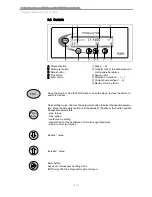
Controls

A Program button

B Parameter button

C Minus button

D Plus button

E Enter button

① Step (1... 6)

② Transfer ratio of the handpiece and

contra-angle handpiece

③ Speed (rpm)

④ Direction of rotation (< - / - >)

⑤ Coolant pump setting (1... 6)

⑥ Maximum torque (Ncm)

PRG

Open the program. Use the PRG button to open the steps; repress the button to

switch to free use.

Para-

me ter

Open setting mode. And Use the parameter button to select changeable parame‐

ters. Press the parameter button until the asterisk (*) flashes at the desired position.

Changeable parameters:

- max. torque

- max. speed

- coolant pump setting

- Transfer ratio of the handpiece and contra-angle handpiece

- Direction of motor rotation

Reduce * value.

Increase * value.

Enter button:

Save set of values/leave setting mode

INTRAsurg 300 Plus: Request maximum torque.


Instructions for use INTRAsurg 300 / INTRAsurg 300 plus
3 Product description | 3.2 Controls

14/66

Summary of Contents for INTRAsurg 300

Page 1: ...Instructions for use INTRAsurg 300 INTRAsurg 300 plus Always be on the safe side...

Page 2: ...Distributed by KaVo Dental GmbH Bismarckring 39 D 88400 Biberach Tel 49 7351 56 0 Fax 49 7351 56 1488 Manufacturer Kaltenbach Voigt GmbH Bismarckring 39 D 88400 Biberach www kavo com...

Page 3: ...0 plus 13 3 2 Controls 14 3 3 Multifunctional foot control 15 3 4 Rating plate for 300 300 plus 16 3 5 Technical data for the 300 300 plus 16 4 First use 18 4 1 Electrical connection 18 4 2 Unpacking...

Page 4: ...49 6 2 1 Automated disinfection 49 6 2 2 Manual disinfection 49 6 2 3 Drying 50 6 2 4 Service inspection and testing after preparation 50 6 3 Sterilisation in a steriliser in compliance with DIN EN 13...

Page 5: ...ly and guarantees zero defects in the material or processing for a period of 12 months from data of purchase subject to the following conditions Upon justified complaints of flaws or a short delivery...

Page 6: ...packaging is visibly damaged on delivery please proceed as follows 1 The recipient of the package must record the loss or damage on the delivery receipt The recipient and the representative of the sh...

Page 7: ...e damage immediately or at least 7 days after the delivery to the de livery company 2 Leave the product and packaging in the condition in which you received it 3 Do not use a damaged product Note Fail...

Page 8: ...Humidity Air pressure Instructions for use INTRAsurg 300 INTRAsurg 300 plus 1 User instructions 1 5 Transportation and storage 6 66...

Page 9: ...ON CAUTION indicates a hazardous situation that can cause damage to property or mild or moderate physical harm WARNING WARNING indicates a hazardous situation that can cause death or serious injury DA...

Page 10: ...mmended annual servicing must be done Yearly safety inspections are required KaVo recommends an annual service check In this service check the safety checks are performed according to IEC 62353 2007 a...

Page 11: ...in ternal components can increase transmission or reduce the electromagnetic im munity of the product Only use accessories recommended by KaVo CAUTION Interactions between devices Effect on proper us...

Page 12: ...ted sterilized according to the section Preparation methods Additional information can be obtained from KaVo www kavo com or your dental supplier For final disposal contact Germany To return an electr...

Page 13: ...enings from penetration of liquids Remove liquids from the inside of the device CAUTION Unintended penetration of liquids Electrical shock Do not immerse the product in a tub like container Check and...

Page 14: ...truction of electronic components Before contacting the hose coupling touch the bottle holder with your hand to release static electricity KaVo recommends that only original KaVo parts be used for ope...

Page 15: ...functional foot control The KaVo INTRAsurg 300 plus has an additional lighting function and recognition function for the INTRA CL light hand and contra angle handpiece Note Additional information on s...

Page 16: ...Para meter Open setting mode And Use the parameter button to select changeable parame ters Press the parameter button until the asterisk flashes at the desired position Changeable parameters max torqu...

Page 17: ...cing the individual steps Press briefly proceed forward press for a long time proceed backwards Double click open selection An acoustic signal confirms proceeding forward backward when the motor start...

Page 18: ...ctured XXXXXXX Serial number REF Material number Type Device type For disposal information see use in accordance with intended purpose GOST R certification 3 5 Technical data for the 300 300 plus Widt...

Page 19: ...length hose for the multifunc tional foot control Only available with the INTRAsurg 300plus 3 5 m Standard motor hose length Mat no 1 001 2651 2 00 m Special length motor hose Mat no 1 004 6825 3 0 m...

Page 20: ...into the device s socket to connect to the mains Both lines L and N are individually fused with T 3 15 H The network frequency can be 50 or 60 Hz Requirement Make sure that the supply voltage is corre...

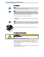
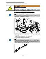
Page 21: ...connected to the device Pull out the INTRAsurg 300 300 plus vertically upward and place on a flat sur face 4 3 Adjust the mains input voltage CAUTION Voltage conducting parts Electrical shock Unplug t...

Page 22: ...ack in the drawer Insert the drawer in the device A code protects the drawer from being incorrectly inserted 1 2 3 4 Instructions for use INTRAsurg 300 INTRAsurg 300 plus 4 First use 4 3 Adjust the ma...

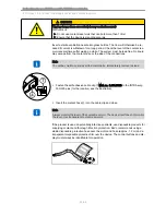
Page 23: ...g danger from excessively heavy coolant reservoir Malfunctions Do not use coolant reservoirs that can hold more than 1 litre Ensure that the device is standing securely In the case of glass bottles in...

Page 24: ...uids must be sterilised Plug in the surgery motor at these surgery hose coupling and tighten with a union nut Follow the separate instructions for use for the motor Place the surgery motor on the moto...

Page 25: ...echanics by lifting the lock Note Insert the pump hose into the pump so that it is not clamped or pinched by the lock Run all hoses relaxed without tension Shove the hoses firmly on the plug in nipple...

Page 26: ...lf adhesive cable clip Mat no 1 001 3348 to the INTRAsurg 300 300 plus for the location see the illustration Insert the coolant hose into the cable clip and close Note Always monitor the level of the...

Page 27: ...e device is not monitored we recommend turning it off for safety reasons and to save energy Note The last saved values are displayed 5 2 Surgical motors CAUTION Incorrectly set parameters Damage from...

Page 28: ...ransferred Check all input values before use Mount the handpiece or angle piece 1 CAUTION Heat transferred from high pressure Burns from touching the high pressure lamp Only operate the motor with the...

Page 29: ...emove the coolant hose from the handpiece or angle piece Twist the handpiece or contra angle handpiece slightly while pulling it off See also 5 1 1 Start up Page 25 5 2 4 Start the motor Start the mot...

Page 30: ...r ratio of the handpiece and contra angle handpiece max speed Direction of motor rotation Coolant pump setting max torque Para meter Press the parameter button A star flashes next to the alterable par...

Page 31: ...Drilling cutting 1 1 3 610 N 1 1 300 40 000 5 5 Grinding Drilling Thread Implant 12 1 3624 N 4 1 C 3 3 1 25 3 300 40 Grinding Drilling Thread Implant 16 1 3624 N 4 1 67 RIC 4 1 18 2 500 45 Grinding Dr...

Page 32: ...again to start the motor Checking the handpieces and contra angle handpieces Check the set transfer ratio and let the motor and handpiece or contra angle hand piece run for 20 seconds at maximum speed...

Page 33: ...e application 5 3 4 Set the coolant flow Para meter Press the parameter button until the asterisk flashes at the coolant flow The flow can be changed in the parameter menu by using the Plus and Minus...

Page 34: ...functional foot control and save it with the enter button 5 3 5 Selecting the handpiece and contra angle handpiece Press the parameter button until the asterisk flashes at the transfer ratio Use the P...

Page 35: ...i clock wise signal W Y Z Move the shift pedal in the direction of the arrow With counterclockwise rotation the rotational direction display flashes and two acoustic signals sound When the motor is st...

Page 36: ...5 3 8 Surgical motor in free use Note This function is only supported by the INTRAsurg 300 plus in conjunction with the INTRA CL light hand and angle pieces The recognition function of the INTRA CL li...

Page 37: ...am The product has a basic program with six programmable steps The current step is shown in the display Press the right button briefly or PRG Press the program button once An acoustic signal confirms...

Page 38: ...entry 5 4 4 Set parameters Select the step to be changed Para meter Switch to the parameter menu by pressing the parameter button See also 5 3 Free use Page 28 The values shown for a step are default...

Page 39: ...use 5 4 5 Limit the number of steps Six steps are saved upon first start up and after setting up the delivery status Example Limiting the steps The number of steps should be limited to four Select ste...

Page 40: ...y Condition at the time of delivery Programme Step Instrument Speed rpm Torque Ncm Pump Direction of motor rota tion 1 27 1 11 1500 55 4 2 27 1 11 50 40 4 3 27 1 11 50 40 4 4 27 1 11 50 40 4 5 27 1 11...

Page 41: ...gle handpieces without the moun ted and peace and contra angle handpiece Para meter Press the parameter button until the asterisk flashes at the transfer ratio Set the correct parameters with the Plus...

Page 42: ...piece The transfer ratio and associated values are shown on the display The user can perform additional calibration with the INTRAsurg Calibration 1 002 3569 27 1 angle piece is required Display of th...

Page 43: ...g input Three acoustic warning signals sound and the read in instrument flashes on the device display with a ques tion mark for example 27 1 Note For safety reasons the motor does not start safety cir...

Page 44: ...ight only shines when actuated spotlight function Default light when the motor starts Move the shift pedal to the left The light is turned on or off When the light is turned on the following appears i...

Page 45: ...or restarts under a minimum load of 5 Ncm 5 5 4 Request maximum torque program See also 5 4 8 Request maximum torque Page 39 5 5 5 Recommended programming when setting a number of im plants one after...

Page 46: ...23 24 25 26 27 28 29 30 correc tion 0 8 0 7 0 6 0 5 0 4 0 3 0 2 0 1 0 0 1 0 2 0 3 0 4 0 5 0 6 0 7 A sterile instrument can also be used for calibration To prevent contamination use a sterile catch pi...

Page 47: ...n the following appears on the display If calibration is unsuccessful the following appears on the display Note The output values are retained in case of interruption or error The calibration automati...

Page 48: ...ch as saline coolant residue blood and saliva with a disposable cloth immediately after use Only use fully functional products for treating patients Observe all current national hygiene regulations Se...

Page 49: ...loth on edges and press so that liquid will not penetrate Remove all residue and dry the device Note After uses that run the risk of infection rinse the coolant lines of the handpieces and contra angl...

Page 50: ...d Observe the necessary measures for infection protection W Y Z Press left button 3 sec The rinsing function is selected See also 5 3 7 Rinsing function Page 33 The rinsing function is shown in the di...

Page 51: ...pplicable for INTRAsurg device parts 6 2 2 Manual disinfection Pull the insertion needle out of the coolant reservoir Open the lock and remove the hose Remove all hoses marked gray including tips and...

Page 52: ...chment of hose connections Check control commands on foot control Check recognition function of INTRAsurg 300 plus Comply with hygiene requirements sterility during the check If there are any sites of...

Page 53: ...icrobiologically appropriate coolant liquid must be used Only use prescribed isotonic saline solution E NaCl 0 9 identified as an infusion solution follow the instructions on the package insert for co...

Page 54: ...eam at 135 1 gravity for at least 4 minutes Note Let the sterilised materials cool and try to the ambient temperature before using them again 6 3 3 Storage Observe all necessary measures for hygiene w...

Page 55: ...not plugged in Plug in the mains power line The wrong handpiece or angle piece is mounted or set on the de vice Adjust the right handpiece or an gle piece on the device Unknown Turn the machine off an...

Page 56: ...ed or set on the de vice Adjust the right handpiece or an gle piece on the device The motor makes a grinding noise The motor is not correctly plugged on or screwed on Firmly insert the motor hose into...

Page 57: ...connec ted to the motor hose Properly plug in the motor Display remark 67 motor not plugged When the motor starts the discon nection of the motor from the hose is detected Plug the hose onto the moto...

Page 58: ...drain the lines remove the insertion needle from the saline solution res ervoir and activate the pump by using the multifunctional foot control until the hoses are free of saline solution Remove the...

Page 59: ...Pump hose short less accumulated volume in the coolant hose less potential dripping Pump hose long large accumulated volume in the coolant hose increased drip ping possible Observe hygiene to prevent...

Page 60: ...5 5188 cut section off the cou pling Mat no 1 001 6462 and the handpiece or angle piece and exchange 7 2 2 Exchange the coolant hose in the motor hose Note Run the new hose straight in the direction o...

Page 61: ...can be ordered under Mat no 1 001 9902 pack age contents 10 units This should be used for applications with an increases infection risk or when the motor hose cannot be prepared according to the exis...

Page 62: ...completely open the inserted hose clip The coolant flow is also affected by the outlet in the handpiece or angle piece A focused water jet should arise Set the pump flow on the device Note To avoid dr...

Page 63: ...ame __________________ Step Instrument Speed rpm Torque Ncm Pump Motor r l Free Instrument Speed rpm Torque Ncm Pump Motor r l Date _______________________ Name __________________ Step Instrument Spee...

Page 64: ...o 0 726 2922 IPX 8 foot control element with 3 5 m connection cable please in quire Mat no 1 004 8276 Steri Set INTRAsurg 300 please inquire Mat no 1 001 4953 includes the fol lowing parts 1x motor ho...

Page 65: ...esidential ones and fa cilities that are directly connected to a public power supply that also sup plies residential buildings Transmissions of voltage fluctua tions or flicker according to IEC 61000...

Page 66: ...EC 61000 4 11 5 UT for 1 2 period 95 interruption 40 UT for 5 periods 60 interruption 70 UT for 25 periods 30 interruption 5 UT for 5 s 95 interruption 5 UT for 1 2 period 95 interruption 40 UT for 5...

Page 67: ...ers such as base stations of mobile tele phones and land radio devices amateur radio stations AM and FM radio and tel evision broadcasters cannot be theoretically predetermined To determine the elec t...

Page 68: ...o the manufacturer s information NOTE 2 These guidelines may not be applicable in every case The spread of electromagnetic waves is absorbed and reflected by buildings objects and people Comment 1 To...

Page 69: ......

Page 70: ...1 001 3529 Fk 2010506_09 en...

Reviews: