


1. Attach the ESD grounding strap to your bare wrist and to a site ESD point.
2. Decide where to position the device in the rack.
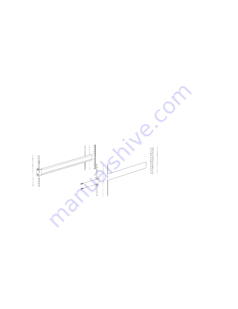
3. Install the rear installation blades. See
.
a. With two mounting screws—and cage nuts and washers if your rack requires them—attach one of
the rear installation blades to the left rear of the rack at the point where you want to mount the
device. Tighten the screws.
b. Position the second rear installation blade at the desired position in the right rear of the rack, so
that it is on the same rack level as the left rear installation blade. If the right and left rear installation
blades are not on the same level, the chassis will rest at an angle in the rack instead of resting flat
and level.
c. With two mounting screws—and cage nuts and washers if your rack requires them—attach the
second rear installation blade to the right rear of the rack at the point where you want to mount
the device. Tighten the screws.
Figure 84: Attaching the Installation Blades to the Rear of the Rack
g050208
4. Prepare the device for mounting.
a. Place the device on a flat, stable surface.
b. Align the mounting brackets along the front or rear of the side panels of the device chassis depending
on how you want to mount the device. For example, if you want to front-mount the device, align
the brackets along the front of the side panel such that the mounting ears are in the front of the
device chassis. See
.
c. Align the holes in the mounting brackets with holes on the side panels of the device chassis.
d. Insert mounting screws into the aligned holes. Tighten the screws.
5. Mount the device.
305
Summary of Contents for QFX3500
Page 1: ...Virtual Chassis Fabric Hardware Documentation Published 2020 11 06...
Page 225: ...Translation The emitted sound pressure is below 70 dB A per EN ISO 7779 201...
Page 229: ...205...
Page 238: ...Unterminated Fiber Optic Cable Warning 214...
Page 246: ...Restricted Access Warning 222...
Page 249: ...225...
Page 257: ...Jewelry Removal Warning 233...
Page 260: ...Operating Temperature Warning 236...
Page 271: ...DC Power Disconnection Warning 247...
Page 275: ...DC Power Wiring Sequence Warning 251...
Page 278: ...DC Power Wiring Terminations Warning 254...
Page 410: ...Figure 130 All QFX5110 VCF g050760 Figure 131 QFX5110 VCF with QFX5100 24Q Leaf Devices 386...
Page 412: ...Figure 132 QFX5100 24Q as a Leaf Device in a QFX5110 VCF 388...
Page 565: ...Table 105 System Information continued Description Field Inventory details 541...


