System Set-Up
41
VIS-CAM Systems
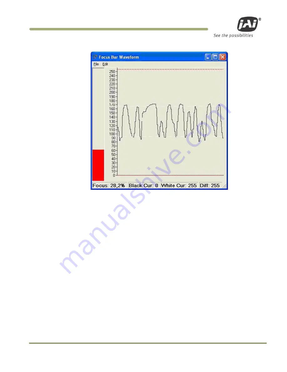
Figure 41.
Focus Bar Waveform display.
5. Gently snug the zoom and focus lens holder thumbscrews against the lens without changing any of
the lens settings.
6. Uncover the license plate by removing the lens focus chart.
7. Use the mouse to move the waveform cursors to the top and bottom of the waveform amplitude
variation. The “Black Cursor” is located at the bottom of the waveform display, and the “White
Cursor” is located on the top of the waveform display.
8. Verify that the waveform amplitude variation (for characters in both direct light and shadow, if
possible) is at least 25 and that no portion of the waveform fully saturates either black or white.
Summary of Contents for VIS-CAM System
Page 1: ...VIS CAM System Vehicle Imaging Subsystem Document Version 10436 Document P N E...
Page 2: ......
Page 12: ...VIS CAM Systems xii List of Tables...
Page 20: ...VIS CAM Systems 8 Preparing for Installation Figure 5 VIS 300 U S Camera options chart...
Page 21: ...Preparing for Installation 9 VIS CAM Systems Figure 6 VIS 350 U S Camera options chart...
Page 22: ...VIS CAM Systems 10 Preparing for Installation Figure 7 VIS 400 U S Camera options chart...
Page 23: ...Preparing for Installation 11 VIS CAM Systems Figure 8 VIS 500 U S Camera options chart...
Page 24: ...VIS CAM Systems 12 Preparing for Installation Figure 9 VIS 300 European Camera options chart...
Page 25: ...Preparing for Installation 13 VIS CAM Systems Figure 10 VIS 350 European Camera options chart...
Page 26: ...VIS CAM Systems 14 Preparing for Installation Figure 11 VIS 400 European Camera options chart...
Page 27: ...Preparing for Installation 15 VIS CAM Systems Figure 12 VIS 500 European Camera options chart...
Page 92: ...VIS CAM Systems 80 Appendix B Figure 90 Lane controller setup...
Page 100: ...VIS CAM Systems 88 Appendix E Figure 98 Operation configuration of Serial port 1...
Page 110: ......
Page 111: ......


