VIS-CAM Systems
40
System Set-Up
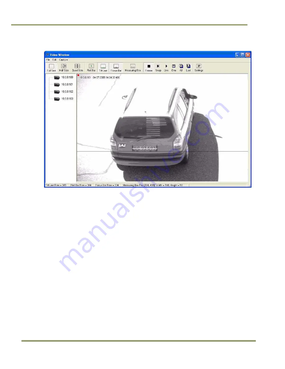
Figure 40.
Focus Bar marker display.
2. Adjust the lens zoom ring until the plate width just barely fits in between the short vertical zoom
markers on the display.
3. Have your assistant tape the lens front-focus chart to the stand so that it appears in-between the
zoom markers. Make sure the black and white bars are vertical in the image.
4. Carefully adjust the lens focus ring until the focus bar waveform display is maximized in
amplitude spread. The “Focus percentage” display shown on the left side of the “Focus Bar
Waveform” window should then be maximized when the picture has got the best focus. If
necessary, readjust the zoom and focus until the width of the plate is just inside the zoom
markers and the waveform spread of the bars is maximized.
Summary of Contents for VIS-CAM System
Page 1: ...VIS CAM System Vehicle Imaging Subsystem Document Version 10436 Document P N E...
Page 2: ......
Page 12: ...VIS CAM Systems xii List of Tables...
Page 20: ...VIS CAM Systems 8 Preparing for Installation Figure 5 VIS 300 U S Camera options chart...
Page 21: ...Preparing for Installation 9 VIS CAM Systems Figure 6 VIS 350 U S Camera options chart...
Page 22: ...VIS CAM Systems 10 Preparing for Installation Figure 7 VIS 400 U S Camera options chart...
Page 23: ...Preparing for Installation 11 VIS CAM Systems Figure 8 VIS 500 U S Camera options chart...
Page 24: ...VIS CAM Systems 12 Preparing for Installation Figure 9 VIS 300 European Camera options chart...
Page 25: ...Preparing for Installation 13 VIS CAM Systems Figure 10 VIS 350 European Camera options chart...
Page 26: ...VIS CAM Systems 14 Preparing for Installation Figure 11 VIS 400 European Camera options chart...
Page 27: ...Preparing for Installation 15 VIS CAM Systems Figure 12 VIS 500 European Camera options chart...
Page 92: ...VIS CAM Systems 80 Appendix B Figure 90 Lane controller setup...
Page 100: ...VIS CAM Systems 88 Appendix E Figure 98 Operation configuration of Serial port 1...
Page 110: ......
Page 111: ......


