Appendix I
95
VIS-CAM Systems
13
Appendix I: Application Note
This Application Note covers the impact of ENSetup software running in parallel to the normal lane controller
operation with FTP file transfer.
13.1
General Instruction of ENSetup Software
ENSetup software is used only for the following 2 purposes;
Initial setup of the camera (lens focus, FOV and zoom adjustment), or
Firmware upgrade.
EN camera uses CONTROL PORT (TCP port 1400) for all command/parameter controls and secure image transfer
as well as TEST PORT (UDP port 1406) for fast setup image transfer.
As soon as the ENSetup discovers the cameras in the network, the software opens CONTROL PORT and TEST
PORT. The camera is a server and the ENSetup is a client in this case. If the lane controller opens the
connection of CONTROL PORT with the camera, this is 2
nd
From the camera’s point of view, 2 clients (ENSetup and Lane Controller) are connected to the server
(=camera.) If one client sends a command to the camera, the camera sends the response to all clients. Also, if
there is any error message from the camera, the camera sends the same error message to all clients.
client for the camera (camera=server.)
Therefore, if ENSetup sends command/status inquiry to the camera via CONTROL PORT, the response messages
are also sent to the Lane Controller. If ENSetup sends Ethernet trigger, the camera sends TRIGGER_ACK and
DATA_READY messages to the Lane Controller as well.
In summary, the ENSetup is NOT intended to be used while the lane controller is running, if you can not afford
to disturb the normal tolling transaction. However, if you have to monitor the live or asynchronously captured
images for debugging purposes, please follow the general steps below.
13.2
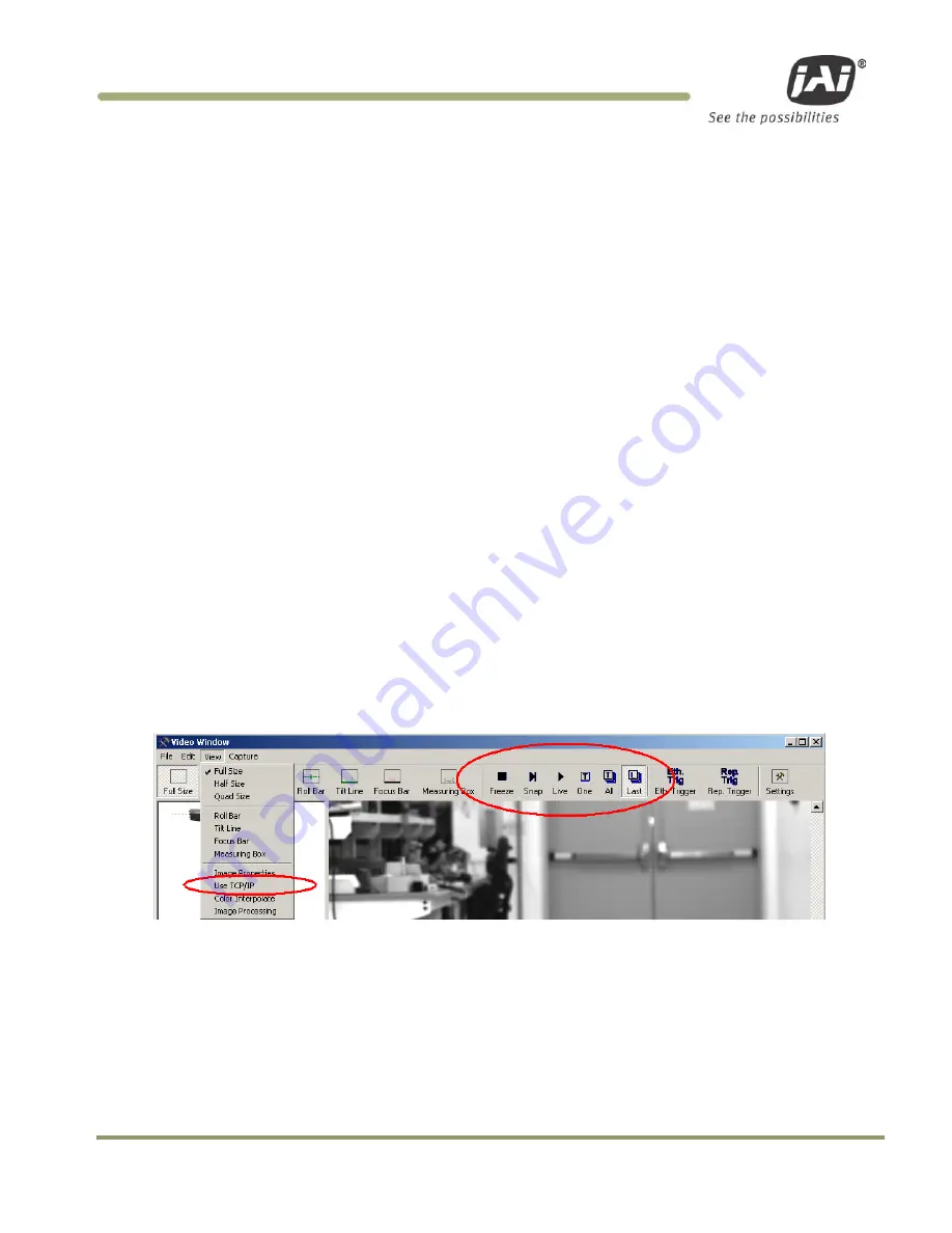
2. UDP image (TEST PORT)
Uncheck “Use TCP/IP” option under View menu item.
Then, the camera sends images over TEST PORT. This TEST PORT maximizes the frame rate of the image.
Primary usage of this PORT is for initial lens adjustment such as focusing and zoom. Within the camera’s
subnet, this is the fastest method of capturing images. If you wish to monitor the image of the camera outside
of camera’s subnet, the router may block the UDP image. Use TCP image in this scenario. See the next “TCP
image” section for the detail.
“Snap”:
Take one snapshot immediately.
“Live”
Capture continuous image. If it is slow PC or low-bandwidth network,
Summary of Contents for VIS-CAM System
Page 1: ...VIS CAM System Vehicle Imaging Subsystem Document Version 10436 Document P N E...
Page 2: ......
Page 12: ...VIS CAM Systems xii List of Tables...
Page 20: ...VIS CAM Systems 8 Preparing for Installation Figure 5 VIS 300 U S Camera options chart...
Page 21: ...Preparing for Installation 9 VIS CAM Systems Figure 6 VIS 350 U S Camera options chart...
Page 22: ...VIS CAM Systems 10 Preparing for Installation Figure 7 VIS 400 U S Camera options chart...
Page 23: ...Preparing for Installation 11 VIS CAM Systems Figure 8 VIS 500 U S Camera options chart...
Page 24: ...VIS CAM Systems 12 Preparing for Installation Figure 9 VIS 300 European Camera options chart...
Page 25: ...Preparing for Installation 13 VIS CAM Systems Figure 10 VIS 350 European Camera options chart...
Page 26: ...VIS CAM Systems 14 Preparing for Installation Figure 11 VIS 400 European Camera options chart...
Page 27: ...Preparing for Installation 15 VIS CAM Systems Figure 12 VIS 500 European Camera options chart...
Page 92: ...VIS CAM Systems 80 Appendix B Figure 90 Lane controller setup...
Page 100: ...VIS CAM Systems 88 Appendix E Figure 98 Operation configuration of Serial port 1...
Page 110: ......
Page 111: ......


