Intel
®
Server System R1000WF Product Family System Integration and Service Guide
37
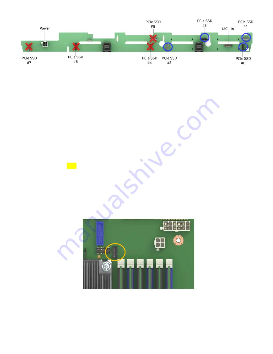
Figure 60. Backplane PCIe* Data Cable Attachments
2.
Carefully attach the P1 end of the PCIe data cable to the PCIe_SSD OCuLink connector on the backplane
3.
Route the PCIe data cable along the closest chassis sidewall to the matching onboard PCIe OCuLink
connector and carefully attach the cable.
4.
Repeat steps 2 & 3 for each PCIe OCuLink cable to be installed.
2.8.2
4 - Port PCIe Switch Cabling
In order to support eight PCIe NVMe SSDs, a 4-port PCIe Switch accessory card and cable kit must be added
to the system.
Required Items:
Intel® Server System R1208WFxxxxx
Intel Accessory
AXXP3SWX08040 –
4-port PCIe Switch Add-in Card
Intel Accessory
TBD –
4-port PCIe Data Cable
1.
Remove the Riser Card #2 assembly from the system
2.
Install the PCIe Switch card in to the add-in slot on the riser card (See section 2.7.2)
3.
Install the 5-pin connector of the PEM cable to the matching 5-pin connector on the PCIe Switch card.
4.
Attach all four (4) OCuLink cable connectors to the OCuLink connectors on the PCIe Switch card
5.
Install the riser card assembly in to the system (See section 2.7.3)
6.
Attach the 5-pin PEM cable from the PCIe Switch card to the matching 5-pin cable connector
(“PEM_SMB”) on the server board
7.
Route the PCIe cable from the PCIe Switch card along the closest chassis sidewall up to the backplane
Cables from Server Board
PCIe SSD # (0-3)
PEM SMB
Connector


