Intel
®
Server System R1000WF Product Family System Integration and Service Guide
7
e)
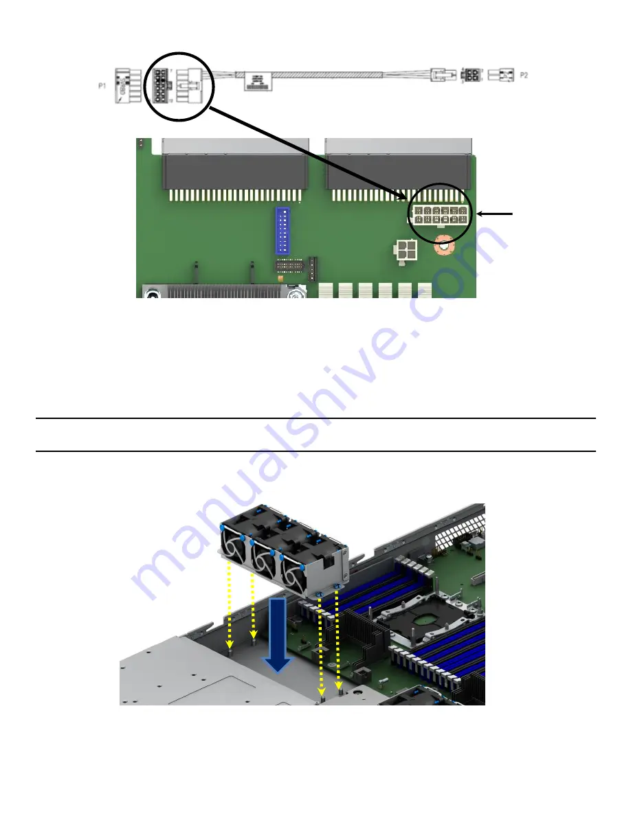
Locate the backplane power cable.
Figure 9. Hot Swap Backplane Power Cable and Onboard Connector
f)
Connect the 2x2 pin cable connector (labeled “P2”) to the matching power connector on the
backplane (silk screened “PWR”)
g)
Route the backplane power cable along the right chassis sidewall, to the area behind the power
supply bay and connect the 2x6 pin cable connector (labeled “SVRBRD”) to the matching 2x6 white
power connector on the server board (silk screened “HSBP PWR”)
Note:
Once the cable is attached on both ends, carefully press the cable as low as possible into the cable
routing channel.
3.
Install the system fan modules
Figure 10. System Fan Assembly Installation
a)
Align the fan assembly with mounting pins on the chassis base and push down until firmly seated
Hot Swap
Backplane
Connector


