background image

Triton Go Product Manual | 

Wiring and Connections

INGENIA | 05/29/2017

83

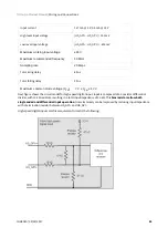
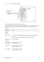
Input current

0.17 mA @ 5 V; 0.5 mA @ 15 V

High level input voltage

( - HS_GPI-) > 150 mV

Low level input voltage

( - HS_GPI-) < -600 mV

Maximum working input voltage

±24 V

Maximum recommended frequency

10 MHz

Sampling rate

20 Msps

Total rising delay

65 ns

Total falling delay

55 ns

Maximum common mode voltage (V

CM

)

-7 V ≤ V

CM

 ≤ 12 V

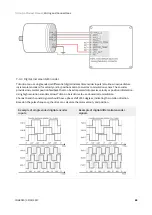
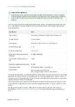
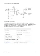
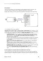
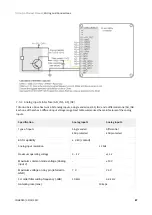
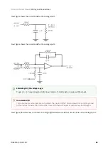
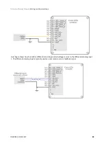
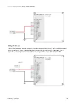
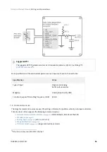
Next figure shows the circuit model for high-speed digital input. Input is composed of a 3-resistor differential 
divider, with 10 k

Ω

 resistors, resulting in a total input impedance of 30 k

Ω

. This 

bias resistors allow both 

single ended and differential input operation

. Noise immunity can be improved by reducing input impedance


with a termination resistor between and HS_GPI-.

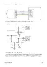
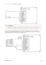
High-speed digital inputs electrical equivalent circuit is the following:

Summary of Contents for Triton Go

Page 1: ...INGENIA CAT S L 8 14 MARIE CURIE ADVANCED INDUSTRY PARK 08042 BARCELONA Triton Go Product Manual Edition 05 29 2017 For the most up to date information visit the online manual...

Page 2: ...and motor connector 24 5 2 Milli Grid connectors mating 25 5 3 Halls and motor temperature connector 27 5 4 Absolute encoder connector 29 5 5 Incremental and Sin Cos encoder connector 31 5 6 USB conne...

Page 3: ...wiring recommendations 78 7 4 8 1 Recommendations for applications witch close feedback and motor lines 78 7 5 I O connections 79 7 5 1 General purpose single ended digital inputs interface GPI1 GPI2...

Page 4: ...s 110 7 7 4 EtherCAT interface 111 7 8 Safe Torque Off STO 112 8 Dimensions 115 8 1 Triton Go with CAN TRI x 48 C C 115 8 2 Triton Go with EtherCAT TRI x 48 E C 116 9 Application Software 118 9 1 Conf...

Page 5: ...A CAT S L Such information is supplied solely for the purpose of assisting users of the product in its installation INGENIA CAT S L rejects all liability for errors or omissions in the information or...

Page 6: ...Triton Go Product Manual General Information INGENIA 05 29 2017 6 3 mailto HELLO INGENIAMC COM 4 http www ingeniamc com Telephone 34 932 917 682 E mail hello ingeniamc com3 Web site www ingeniamc com4...

Page 7: ...power source wait at least 10 seconds before touching any parts of the controller that are electrically charged or hot 3 3 Precautions The following statements should be considered to avoid serious in...

Page 8: ...rm factor its capability to operate up to 110 C and the bunch of features that come packed with it makes Triton a valid OEM for critical size applications The Triton Go Servo Drive has been designed w...

Page 9: ...05 29 2017 9 6 http doc ingeniamc com display TR Triton Core Product Manual Product Ordering part number Status Image Triton Core6 TRI 7 48 C P TRI 4 48 C P TRI 1 48 C P TRI 7 48 E P TRI 4 48 E P TRI...

Page 10: ...Part numbers have changed from version 1 0 0 due to a current re scaling of the whole product range Follow this equivalence to identify your old Triton Version 1 0 0 1 1 0 or later TRI 8 48 C P TRI 7...

Page 11: ...BLDC mode 0 67 ARMS 3 33 ARMS with heatsink 5 6 ARMS with heatsink Nominal phase continuous current DC mode 1 ADC 5 ADC with heatsink 6 3 ADC with heatsink Maximum phase peak current 1 ADC continuous...

Page 12: ...ent sensing Precision current sense on phases A B Phase C is generated digitally Accuracy is 1 full scale 10 bit ADC resolution Sensors for commutation brushless motors Digital Halls Trapezoidal Analo...

Page 13: ...c 24 V tolerant 2 x non isolated high speed differential digital inputs HS_GPI1 HS_GPI2 5 V logic 24 V tolerant 1 x 10 V differential analog input 12 bits AN_IN2 24 V tolerant 1 x 0 V 5 V single ended...

Page 14: ...utputs and feedbacks Supply inverse polarity protection High power transient voltage suppressor 600 W peak TVS diode Can drive an external power braking resistor in case of re injection up to 7 A Safe...

Page 15: ...ironmental and mechanical specifications Part number TRI x 48 C C TRI x 48 E C Cold plate temperature 40 C to 85 C full current with appropriate heatsink 85 C to 110 C derated current Heat dissipation...

Page 16: ...pable of providing the nominal current from 25 C to 85 C temperature measured in the coldplate with a 1 2 C W heatsink attached by means of a low thermal resistance interface material Above 85 C a cur...

Page 17: ...how positive correlation in a proportional ratio PWM switching frequency similar to DC bus voltage the PWM switching frequency directly affects the commutation losses Typically 20 kHz is the default v...

Page 18: ...ge 48 V the same nominal current can be reached with a less restrictive heatsink when DC bus voltage is lower Also other environmental parameters can relax the required heatsink thermal resistance to...

Page 19: ...s With 1 2 C W heatsink attached Considering 90 of maximum temperature This graphic shows the maximum current with respect to coldplate temperature assuming a 1 2 C W heatsink attached This graphic sh...

Page 20: ...n when motor is off exit motor enable mode as this will switch off the power stage 4 4 4 Improving heat dissipation with a heatsink A heatsink is required to reach the nominal current at any ambient t...

Page 21: ...m air space around the drive Place Triton in inverted vertical position with heatsink face up Use a good thermal interface material to improve the heat dissipation If housed use a good thermal conduct...

Page 22: ...Triton Go Product Manual Product Description INGENIA 05 29 2017 22...

Page 23: ...9 2017 23 12 http doc ingeniamc com display TR Triton Core Product Manual 5 Connectors Guide This chapter details the Triton Go Servo Drive TRI x 48 y C connectors and pinout For a pin header board op...

Page 24: ...nal block Phoenix Contact 175129313 Pin Signal Function 1 PH_A Motor phase A Positive for DC and voice coils 2 PH_B Motor phase B Negative for DC and voice coils 3 PH_C Motor phase C Do not connect fo...

Page 25: ...tion see power supply wiring see page 55 motor and shunt braking resistor see page 59 and protective earth see page 52 wiring sections 5 2 Milli Grid connectors mating All Triton Go Servo Drive signal...

Page 26: ...id 0 pageSize 25 18 http www digikey ca product detail en molex llc 0503948051 02 B6 0503948051 02 B6 ND 6047275 Pre assembled wires Description Black 26 AWG pre crimped jumper cable 50 8 mm Note ther...

Page 27: ...2 row Milli Grid 2 mm pitch header Molex 87832 100619 Pi n Signal Function 1 PE Cable shield connection Internally connected to drive mounting plate 2 5V_OU T 5 V 200 mA max shared with other connect...

Page 28: ...hen digital halls are selected See Feedback connections see page 64 for further information about different feedbacks wiring Mating Descriptio n 2 00mm Pitch Milli Grid Receptacle Housing 10 Circuits...

Page 29: ...tch header Molex 87832 080621 Pin Signal Function 1 PE Cable shield connection Internally connected to drive mounting plate 2 3 3V_OUT 3 3 V 200 mA max for absolute encoder 3 5V_OUT 5V 200mA max suppl...

Page 30: ...epts also single ended signals in this case connect clock and data positive signals only See Feedback connections see page 64 for further information about different feedbacks wiring Mating Descriptio...

Page 31: ...Molex 87832 100623 Pin Signal Function 1 PE Cable shield connection Internally connected to mounting plate 2 5V_OUT 5 V 200 mA max shared with other connectors 3 GND_D Ground 4 3 3V_OUT 3 3 V 200 mA m...

Page 32: ...see page 64 for further information about different feedbacks wiring Mating Descriptio n 2 00mm Pitch Milli Grid Receptacle Housing 10 Circuits with Center Locking Ramp and Side Polarization Keys Imag...

Page 33: ...onnector P5 Connector 5 pin vertical micro USB connector Wurth Electronics 61410515072125 Pin Signal Function 1 USB_SUPPL Y USB 5 V supply input Used to power logic circuits when no external power sup...

Page 34: ...3tlJQg 3d 3d 29 http es farnell com molex 68784 0002 cable ass usb a to micro usb b dp 1617586 Notes Avoid applying excessive lateral forces to the USB connector Micro USB connection allows drive conf...

Page 35: ...ion 1 PE Cable shield connection Internally connected to mounting plate 2 GND_D Ground 3 HS_GPI1 PULSE PWM High speed digital differential input 1 Command source Pulse input Feedbacks PWM input 4 HS_G...

Page 36: ...er 14 GPO4 Digital output 4 open collector with weak pull up to 5 V can be configured as brake driver 15 GND_D Ground 16 5V_OUT 5 V 200 mA max shared with other connectors 17 NC Not connected 18 AN_IN...

Page 37: ...30 V and can be used with panel indicators powered at 12V or 24V just ensure current does not exceed 25 mA All the inputs and outputs are tolerant to 30 V therefore they can be wired to PLC interface...

Page 38: ...illi grid 2mm 26way dp 1393610 ost 51110 2651 selectedCategoryId categoryNameResp Todas 2Blas 2Bcategor 25C3 25ADas searchView table iscrfnonsku false 39 http www digikey es product search es keywords...

Page 39: ...ation about crimping terminals and cables 5 8 RS485 interface connector P7 Connector 6 pin 2 row Milli Grid 2 mm pitch header Molex 87832062840 Pin Signal Function 1 PE Cable shield connection Interna...

Page 40: ...ompatible with serial RS422 Please see Communications see page 104 page for further information Mating Descriptio n 2 00mm Pitch Milli Grid Receptacle Housing 6 Circuits with Center Locking Ramp and S...

Page 41: ...w Milli Grid 2 mm pitch header Molex 87832062842 Pin Signal Function 1 STO_COMMON Safe Torque Off common optocoupler LEDs cathode ISOLATED 2 GND_D Ground not isolated 3 STO_1 Safe Torque Off input 1 p...

Page 42: ...umpers Sullins Connector SPN02SVEN RC43 between pins 1 2 3 4 5 6 See Safe Torque Off STO see page 112 for operation information Mating Descriptio n 2 00mm Pitch Milli Grid Receptacle Housing 6 Circuit...

Page 43: ...header Molex 87832040645 The network GND spacer is a SMD mounted female spacer Wurth Electronics 9774015151R46 Pin port 0 and port 1 have identical pinouts Signal Function M2 5 female screw NETWORK_GN...

Page 44: ...nterface accessible without isolation Please see Communications see page 104 page for further information Mating Descriptio n 2 00mm Pitch Milli Grid Receptacle Housing 4 Circuits with Center Locking...

Page 45: ...52 http es farnell com te connectivity 1 1546410 1 rj45 ethernet connector jack 8 dp 1769889 ost 1 1546410 1 selectedCategoryId categoryNameResp Todas 2Blas 2Bcategor 25C3 25ADas searchView table iscr...

Page 46: ...CAN connectors TRI x 48 C C P9 P10 Connectors 2x CAN connectors are 4 pin 2 row Milli Grid 2 mm pitch header Molex 87832040653 Pin Signal Function CAN OUT P9 1 CAN_TERM 120 termination resistor conne...

Page 47: ...le the CAN termination by placing a 2 mm pitch jumper between pins 1 and 3 of connector P9 CAN OUT Sullins Connector SPN02SVEN RC54 The termination jumper should only be placed on P9 using it P10 will...

Page 48: ...xt to the CAN EtherCAT connectors shared with EtherCAT option EtherCAT communication 4 LEDs next to the CAN EtherCAT connectors 2 LEDs shared with CAN option 6 1 Power and operation signalling LEDs Tw...

Page 49: ...es the status of the CAN physical layer and errors due to missed CAN messages sync guard or heartbeat Next table the meaning of the ERROR LED states ERROR LED state Concept Description Off No error De...

Page 50: ...equence of 2 short flashes 200 ms separated by an off phase 200 ms The sequence is finished by a long off phase 1000 ms Triple flash Sequence of 3 short flashes 200 ms separated by an off phase 200 ms...

Page 51: ...ication controller failure For high severity errors inside the Triton Go Servo Drive an special LED state has been developed Status Signalling RUN LED state ERROR LED state Internal error Interleaved...

Page 52: ...ing the users Moreover a proper connection to PE prevents many of the noise problems that occur operating a servo drive Triton Go Servo Drive provides the following earth ground connection points whic...

Page 53: ...lose as possible to power supply cables In order to avoid ground loops it is a good practice to have a central earth connection point or bus for all the electronics of the same bench If multiple drive...

Page 54: ...tor housing 3 Shield I O signals and communication cables The clamp has to be selected according to the shielded cable diameter ensuring a good support and connection between the cable shield and the...

Page 55: ...ke sure that the voltage rating of the power supply does not exceed the voltage rating of the motor otherwise it could be damaged The current should be the one able to provide the phase peak current o...

Page 56: ...ame power supply recommended for TRI 4 48 y C 300 W TDK Lambda PFE500 F48 48 10 5 Switching closed frame power supply recommended for TRI 7 48 y C 500 W 7 2 2 Power supply connection Triton Go logic a...

Page 57: ...same power supply connect them in star topology for reducing cable impedance and common mode coupled noise That is connect each drive to the common supply using separate wires for positive and return...

Page 58: ...ed wire sections Connection Minimum wire size Maximum wire size Stranded wire preferred 0 5 mm2 20 AWG 1 5 mm2 16 AWG Solid wire 0 5 mm2 20 AWG 1 5 mm2 16 AWG Wire ferrules For low power applications...

Page 59: ...l as electromagnetic emissions and immunity For best immunity use twisted and shielded 2 wire cables for the DC power supply This becomes crucial in long cable applications Avoid running supply wires...

Page 60: ...or each phase could also work the EMI reduction would be much lower than passing all the phases through the same choke Proper three phase motor choke wiring In order to minimize the capacitive couplin...

Page 61: ...he phases through the same choke Proper DC motor choke wiring In order to minimize the capacitive coupling of the motor wires and therefore cancelling the effect of the common mode rejection effect th...

Page 62: ...ecommended since it provides lower contact resistance Due to the connector s size the maximum allowed ferrule size is 0 5 mm2 Ensure the insulator does not exceed 3 5 mm connector pitch Following tabl...

Page 63: ...s between the Triton Go outputs and the cable The inductors must be magnetically shielded and must be rated for the motor surge current Typical values are around 100 H 7 3 4 Shunt braking resistor Whi...

Page 64: ...encoder Sin Cos encoder see page 72 Absolute encoder see page 74 Additional feedback connections can be found on I O connector see page 79 Hot surfaces Be careful shunt resistor may have hot surfaces...

Page 65: ...he position direction and velocity of the rotor Next figures show examples of digital halls signals Digital halls signals example 60 option Digital halls signals example 120 option Digital halls can b...

Page 66: ...z Sampling frequency 10 ksps Type of sensors Open collector Logic output Push pull output Pull up resistor value 1 k The pull up is activated only when the drive is configured to use digital hall sens...

Page 67: ...connections and wires 7 4 2 Analog Halls interface The Triton Go Servo Drive can operate with analog Hall sensors also known as linear halls as feedback option Signals provided by these sensors are ty...

Page 68: ...rking frequency 1 kHz 1st order filter cutting frequency 3dB 10 kHz Sampling frequency 10 ksps Voltage range 0 5 V 10 bits Maximum voltage range 0 3 5 3 V Next figure illustrates the circuit model for...

Page 69: ...The encoder provides incremental position feedback that can be extrapolated into precise velocity or position information Using high resolution encoders allows Triton Go Servo Drive to use sinusoidal...

Page 70: ...ntial line receiver with an hysteresis comparator is used The high signals ENC_A ENC_B and ENC_Z are pulled up to 5 V and the low signals ENC_A ENC_B and ENC_Z are biased to 2 5 V This arrangement let...

Page 71: ...Triton Go Product Manual Wiring and Connections INGENIA 05 29 2017 71 Next figure shows the circuit model of the digital encoder inputs...

Page 72: ...ide a pair of quadrature sine and cosine signals as the motor moves which frequency depends on the motor speed The signals may be generated by optical or magnetic means For noise immunity the signals...

Page 73: ...ommended working frequency 1 kHz used as analog encoder 10 MHz used as digital encoder 1st order filter cutting frequency 3 dB 6 MHz Sampling rate analog 10 ksps Maximum readable pulse frequency digit...

Page 74: ...ans it is not necessary to move to a reference position as with incremental type encoders Next table shows the absolute encoder inputs electrical specifications Specification Value Type of inputs Non...

Page 75: ...4 6 Digital input feedback PWM encoder Triton Go Servo Drive can also use a PWM encoder connected through the I O and LEDs connector as a feedback element A PWM encoder provides a Pulse Width Modulate...

Page 76: ...PWM encoders can be used Further specifications about the PWM input can be found in I O connection section see page 79 Next figure illustrates PWM feedback input for different rotor positions Next fi...

Page 77: ...bout connections and wires Potentiometer Typically a potentiometer is used as a postition feedback providing a a voltage proportional to the rotor position The following picture shows how to connect a...

Page 78: ...lp in elimination of noise because disturbances induced in twisted pairs Twisted pairs help in elimination of noise due to electromagnetic fields by twisting the two signal leads at regular intervals...

Page 79: ...vo Drive provides various inputs and output terminals for parameter observation and drive control options These inputs can also be used for some feedback purposes see Feedback connections see page 64...

Page 80: ...Input current 0 17 mA 5 V 1 mA 15 V High level input voltage 4 V Vin 24 V Low level input voltage 0 Vin 1 V Input impedance 30 k 1st order filter cutting frequency 3 dB 20 kHz Sampling rate 1 ksps Max...

Page 81: ...llustrate the connection of PNP and NPN three wire sensors in input GPI1 same wiring can be used for GPI2 GPI3 and GPI4 Pin 16 5V_OUT can be used as a supply source Non isolated I O Triton Go Inputs a...

Page 82: ...rential and single ended ESD capability IEC 1000 4 2 ESD 12 kV air 6 kV contact GPI Pull up resistors Pull up resistors ensure the desired logic state when the sensor transistor or relay is in off sta...

Page 83: ...Total falling delay 55 ns Maximum common mode voltage VCM 7 V VCM 12 V Next figure shows the circuit model for high speed digital input Input is composed of a 3 resistor differential divider with 10 k...

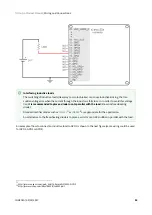
Page 84: ...used for HS_GPI2 Single ended operation of HS_GPI In order to use the high speed digital input in single ended mode connect HS_GPIx to GND and HS_GPI to the desired input signal Non isolated I O Trito...

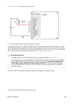
Page 85: ...85 Triton Go Servo Drive high speed digital inputs can be used for connecting three wire sensors Next figures illustrate the connection of PNP and NPN three wire sensors in input HS_GPI1 Same wiring c...

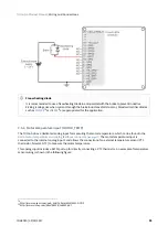
Page 86: ...re HS_GPI pull up resistors Pull up resistors ensure the desired logic state when the sensor transistor or relay is in off state NPN pull up resistor value must be chosen in order to ensure a positive...

Page 87: ...ltage range Next table summarizes the main features of the analog inputs Specification Analog input 1 Analog input 2 Type of inputs Single ended ESD protected Differential ESD protected ESD capability...

Page 88: ...connect an analog single ended source to the Triton Go Servo Drive analog input 1 Extending AN_IN1 voltage range To get a 0 10 V input range in AN_IN1 input place a 71 5 k resistor in series with the...

Page 89: ...Connections INGENIA 05 29 2017 89 Next figure shows how to interface differential and single ended voltage sources to the differential analog input 2 The differential analog input is typically used as...

Page 90: ...protected Next table shows their main features Specification Value Number of outputs 4 Type of output Open drain output with weak pull up to 5 V ESD protected Overload short circuit and over temperatu...

Page 91: ...V as high level voltage can be connected directly to the digital output A wiring example for GPO1 is shown in the next figure same wiring could be used for GPO2 GPO3 or GPO4 Non isolated I O Triton Go...

Page 92: ...t require 24V as high level voltage can also be interfaced with GPO For this option an external power supply is needed The load can be connected with a pull up to 24V or directly switched with the GPO...

Page 93: ...ductive loads The switching of inductive loads like relays or motor brakes can cause inductive kicking that is a sudden voltage rise when the current through the inductor is falls to zero In order to...

Page 94: ...d 24 V Further specifications can be found in Digital outputs interface see page 90 Next figure show how the typical connection using the main supply as brake power supply Motor brake operation For br...

Page 95: ...t is connected to the internal analog input 3 and allows the connection of an external temperature sensor PTC thermistor bimetal NTC to measure the motor temperature This analog input includes a 967 p...

Page 96: ...quency 3dB 800 Hz 7 6 Command sources The target or command sources are used for setting a reference for position velocity or torque controllers Triton Go Servo Drive supports the following command so...

Page 97: ...tion as a form of input command Supported network interfaces for Triton Go Servo drive are CAN CANopen protocol USB RS 485 and EtherCAT USB interface is not suitable for long distances or noisy enviro...

Page 98: ...o Servo Drive has two 12 bit analog inputs a single ended one with 0 V to 5 V range AN_IN1 and a differential one with 10 V range AN_IN2 Refer to I O Connections see page 79 for further details about...

Page 99: ...lse signal is usually a square signal and each pulse on this signal causes the controller to move the motor one step in that direction This command source can be used only for position mode This comma...

Page 100: ...sets a position velocity or torque target from the duty cycle value of a PWM signal PWM command has to be interfaced with the high speed digital input 2 HS_GPI2 Further details about this input can b...

Page 101: ...with a target of 0 rad 0 rpm or 0 N m and higher or lower values indicate the target in a different rotating direction That is a duty cycle of 0 corresponds with the maximum position velocity or torq...

Page 102: ...clockwise rotation and logic high or 1 for counter clockwise rotation In this mode a duty cycle of 0 corresponds with a target of 0 rad 0 rpm or 0 N m and a duty cycle of 100 corresponds to the maximu...

Page 103: ...d used as position target A gearing ratio between the motors input counts to output counts ratio can be configured via software Encoder following command source is implemented by connecting the input...

Page 104: ...can be used to connect the Triton Go with Ingenia Motion Lab81 suite or a custom application built with the supplied controller libraries With the objective of configure and diagnostic CAN communicati...

Page 105: ...connected on Triton Go Do not rely on an earthed PC to provide the Triton Go Servo Drive earth connection The drive must be earthed through a separate circuit Avoid creating ground loops by using iso...

Page 106: ...n resistor 120 termination resistor on RX channel Next figure illustrates how to connect Triton Go Servo Drive with a host in a point to point configuration Termination resistor The use of termination...

Page 107: ...the RX terminals of the next device An example of daisy chain wiring of multiple Triton Go is shown in the next figure Termination resistor for daisy chain In daisy chain connection termination resist...

Page 108: ...Since Triton Go has two CAN connectors wiring from previous device and to next device can be done using different connectors CAN IN and CAN OUT Pins 2 3 and 4 of those connectors are connected pin to...

Page 109: ...ton Go Servo Drive includes a termination resistor on board The resistor is connected between CAN_H and CAN_TERM To activate the resistor connect pins 1 CAN_TERM and 3 CAN_L on CAN OUT connector The c...

Page 110: ...o CAN dual channel interface High speed CAN channels in two separate RJ 45 connectors Cable adapter to 9 pin D SUB CAN Vector Informati k VN1630 USB to CAN or CAN FD four channel two connectors interf...

Page 111: ...ation technology test and measurement and many other applications Next table summarizes the features of the Triton Go EtherCAT interface EtherCAT specific features Ports available 2 LED Signals Status...

Page 112: ...ault In order to activate the power stage and therefore allow the motor operation two differential inputs must energized These inputs activate two optocouplers connected in series that enable the Trit...

Page 113: ...nnector includes two 5V pins and a GND pin Next figures shows how to connect the STO inputs with an external power supply and with the self 5V_OUT pins STO firmware notification An STO stop is notifie...

Page 114: ...5 29 2017 114 Overriding STO In applications where the STO will not be used this function can be disabled with the use of three standard 2 mm jumpers The connection of pins 1 2 3 4 and 5 6 will activa...

Page 115: ...CAT Both have a 43 mm x 45 mm footprint 23 5 mm height and 4 x 3 3 mm holes in a 37 mm x 37 mm square for M3 screws mounting 8 1 Triton Go with CAN TRI x 48 C C All dimensions are in mm All tolerances...

Page 116: ...riton 8 2 Triton Go with EtherCAT TRI x 48 E C All dimensions are in mm All tolerances 0 2 mm 3D Model For further detail download the STEP 3D model and PDF 3D88 for this variant Note that the model i...

Page 117: ...29 2017 117 89 http ingeniamc com support triton 3D Model For further detail download the STEP 3D model and PDF 3D89 for this variant Note that the model is simplified it does not show all the intern...

Page 118: ...ab90 suite The software package includes USB drivers 9 2 Applications If you want to make your own application to communicate with the Triton Go and develop standalone or multiaxis systems you can use...

Page 119: ...ervotecnica com info servotecnica com Norway ELECTRO DRIVES AS www electro drives no firmapost electro drives no Portugal MEC NICA MORDERNA www mecmod com pt vendas mecmod com Russia AVI SOLUTIONS www...

Reviews: