IDEAL Viscount GTE 14 Installation, Assembly And Servicing Download Page 32

32

Ideal Viscount GTE 

- Installation, Assembly & Servicing

1

2

4

5

2

3

VIS5114

ASSEMBLY 

43

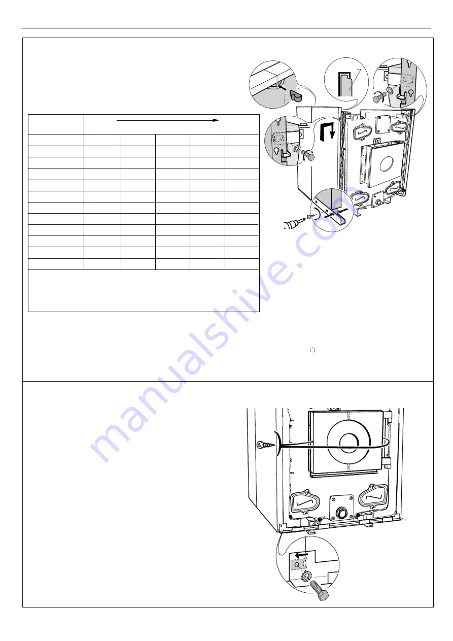
Assembling the Side Casing Panels

Length and arrangement of panels for the boiler
model

Put the 

furnace door panel 

in place (package 

FA5 or

FA

6) and fasten with two ø 3.94 x 12.7 tapping screws.

The furnace door panel may be cut in two at the micro-
joints.

Fit two Rapid nuts in the bottom of the front side panels.

Fix 

the casing support lower crosspiece 

(package 

FA5

or FA

6) by means of two H 6x20 screws and two serrated

washers.

First assemble the panels on the front 

using

the assembly length table opposite and
continue up to the rear section 

.

Fix the front side panels 

to the positioning

brackets with H 8 x 16 screws and serrated
washers 

.

Push the insulating material into the top of the
side panels and fasten the panels 

 to the

lower rails by means of the self-tapping screws
with the electric screwdriver (2 screws per
panel)   .

Fasten the side panels to each other with the
clips 

.

Type of

Boiler

GTE 14

800

600

600

GTE 15

940

600

600

GTE 16

1050

600

600

GTE 17

940

600

400

400

GTE 18

1050

600

400

400

GTE 19

940

600

600

400

GTE 20

940

600

600

600

GTE 21

1050

600

600

600

GTE 22

940

600

600

400

400

GTE 23

1050

600

600

400

400

GTE 24

940

600

600

600

400

GTE 25

1050

600

600

600

400

      400 mm long panel in Package FA 10
      600 mm long panel in Package FA 11
      800 mm long panel in Package FA 7
      940 mm long panel in Package FA 8
      1050 mm long panel in Package FA 9

Side Panels Length in mm

FRONT

REAR

44

Assembling the Furnace Door and Lower Crosspiece Panels

VIS5115

1

2

4

Summary of Contents for Viscount GTE 14

Page 1: ...Fired heating boilers should be read in conjunction with the general technical data tables enclosed and any other technical publication supplied with the burner CAUTION To avoid the possibility of injury during the installation servicing or cleaning of this appliance care should be taken when handling edges of sheet steel components 94863157 85254022 A 05 01 ...

Page 2: ...GTE range are pressurised hot water boilers designed for connecting to a flue pipe which require a separate automatic fuel oil or gas burner The heat output of Viscount GTE boilers is between 754 and 1450 kW Models available Viscount GTE Boiler with standard control panel designed to be connected to the electrical cabinet Viscount GTE De Luxe Boiler with De Luxe control panel providing additional ...

Page 3: ...2 34 7 13 8 2 4 0 96 3249 7162 88 64 19 5 0 55 1166 90 4 3192 0 61 1293 16 928 3166 870 2968 731 161 14 5 6 2 5 1 3422 7544 94 55 20 8 0 59 1250 96 4 3403 0 65 1377 17 986 3364 928 3166 769 169 15 6 2 6 1 04 3601 7938 100 5 22 1 0 62 1314 102 4 3616 0 69 1462 18 1044 3562 986 3364 807 177 17 5 7 2 7 1 08 3780 8333 106 4 23 4 0 66 1399 108 5 3831 0 73 1547 19 1102 3760 1044 3562 845 186 19 7 6 2 85...

Page 4: ... 139 7 450 2 10 2105 259 355 130 175 20 1760 1670 1483 2132 5 14 1785 1744 1488 188 139 7 450 150 31 19 2245 324 355 130 175 20 1760 1670 1594 2243 5 15 1896 1966 1488 189 139 7 450 150 30 18 2355 269 355 130 175 20 1760 1670 1705 2354 5 16 2007 1966 1488 210 139 7 500 370 9 3 2445 321 355 130 175 20 1760 1670 1816 2465 5 17 2118 2188 1504 236 159 500 370 8 4 2555 265 355 130 175 20 1760 1670 1927...

Page 5: ...iler to the system making sure you comply with minimum clearance dimension D If A 1 2 m door opening side A 0 5 m If A 0 5 m A 1 2 m door opening side adapt the dimensions on the basis of the dimensions of the burner when the door is open B 1 5 m adapt the dimensions on the basis of the dimensions of the burner GTE 14 15 16 17 18 19 20 21 22 23 24 25 L 2105 2245 2355 2445 2555 2645 2845 2955 3045 ...

Page 6: ... for Space Heating and Hot Water Supply BS 5449 PT 1 Hot Water Systems BS 5854 Flues and Flue Structures in Buildings BS 5885 Pt 1 Gas Burners with outputs of 60kW upwards BS 6644 Installation of Gas Fired Boilers BS 6880 Low Temperature Hot Water Heating Systems BS 6891 Low Pressure Gas Pipework British Gas Industrial Gas Fired Boilers and Publication No IM 11 Air Heaters General Recommendations ...

Page 7: ...d on the bottom of the front of the boiler Fit a quarter turn valve on the opening to remove the sludge Sludge removal leads to the draining of large quantities of water so remember to refill the system after the operation 586m m 150mm 2 tapped sludge removal hole VIS5060 5 CHIMNEY CONNECTION The high performance features of modern boilers and their use in specific conditions as a result of the ad...

Page 8: ...pplied with a plain plate The maximum cutout dimensions are 500 x 700 mm Fit a measuring point ø 10 mm hole on the flue in order to adjust the burner combustion check 815mm F Ø chimney connection 586mm 586mm K VIS5061 GTE 14 15 16 17 18 19 20 21 22 23 24 25 ø F mm 450 450 450 500 500 500 500 K mm 10 19 18 3 4 25 24 23 2 1 20 21 plain plate plain plate plain plate plain plate Plain plate Dimension ...

Page 9: ...nd upon model Standard accessory kit 1 package contents depend upon model Additional accessory kit 1 package contents depend upon model Plain furnace plate 1 1 1 1 1 1 1 1 1 1 1 1 Flue gas connection plate ø 450 1 1 1 with opening ø 500 1 1 1 1 Plain flue gas connection plate 1 1 1 1 1 Flue gas box 1 1 1 1 1 1 1 1 1 1 1 1 Distributing tube fitting 1 1 1 1 1 1 Flow switch and technical instructions...

Page 10: ... 3 1 1 1 1 1 1 1 1 1 1 1 1 De Luxe control panel Package FA 2 1 1 1 1 1 1 1 1 1 1 1 1 Control Panel GTE boiler Number of sections 14 15 16 17 18 19 20 21 22 23 24 25 Burner plate with 165 186 210 240 or 295 ø hole 1 1 1 1 1 1 1 1 1 1 1 1 Smokehood plate with 400 ø opening or plain smokehead plate 1 1 1 1 1 1 1 1 1 1 1 1 Accessories Available as an Option Tools Required JD TE or JD TE Plus assembly...

Page 11: ...7 GTE 18 GTE 19 GTE 20 GTE 21 GTE 22 GTE 23 GTE 24 GTE 25 1 1 1 1 1 1 1 1 1 1 1 1 9 10 11 12 13 14 14 15 16 17 18 19 3 3 3 3 3 3 4 4 4 4 4 4 1 1 1 1 1 1 1 1 1 1 1 1 151 8228 0002 Special Special intermediate intermediate Special intermediate 104 8228 0003 Front Front Front 104 8228 0004 Rear Rear Rear VIS5062 The number of sections of each type is provided in the table below ...

Page 12: ...enough clearance at the rear of the boiler for water connections see 4 1 of the instructions and the distributing tube see 2 of the instructions and fig 23 in this booklet Fit the rear section on the frame behind the fastening brackets see detailed drawing and prop it up Insert the lower assembly rods in the holes of the rear section and the fastening brackets of the frame in order to position the...

Page 13: ...section gently and simultaneously onto both nipples of the rear section with a hammer and a piece of wood positioned in line with the bores Put the assembly tool in position Tighten gradually so as to bring together the upper and lower connections evenly and simultaneously 8 9 Assemble the remaining intermediate sections one by one to the procedure stated in figures 3 4 5 6 7 and 8 First assemble ...

Page 14: ... as the assembly rods are used to make the boiler body integral with the frame Stop tightening as soon as the gap between the spring spires is equal to about 2 mm 11 Fitting the Upper and Lower Assembly Rods 12 Fitting the Upper and Lower Assembly Rods Put in place the upper assembly rods in the two front and rear lugs Mount the two crosspieces supplied in package FA5 FA6 with their bends turned b...

Page 15: ...two holes Place the expansion spring and washer on the rear of each rod Stop tightening the nuts as soon as the gap between the spires of the springs is about 1 mm B B B B A A A A 520 mm long 520 mm long Rear Front Rear Front 420 mm long 420 mm long 520 mm long 520 mm long GTE 14 420 mm long 420 mm long 520 mm long 520 mm long 420 mm long 520 mm long 520 mm long 520 mm long 420 mm long 520 mm long...

Page 16: ...g 420 mm long 520 mm long 520 mm long 420 mm long 420 mm long 520 mm long 520 mm long 420 mm long 420 mm long 420 mm long 520 mm long 520 mm long 520 mm long 420 mm long 420 mm long 520 mm long 520 mm long 520 mm long 420 mm long 420 mm long 420 mm long C C C C C C C C C C C C D D D D D D D D D D D D VIS5076 1 mm 1 mm B C D B C D 1 mm A E Rear Front Rear Front Rear Front GTE 16 GTE 17 GTE 18 ...

Page 17: ...0 mm long 420 mm long 385 mm long 520 mm long 420 mm long 520 mm long 520 mm long 420 mm long 385 mm long 520 mm long 420 mm long 520 mm long 520 mm long 520 mm long 385 mm long 520 mm long 420 mm long 520 mm long 520 mm long 520 mm long 385 mm long 520 mm long 420 mm long C C C C C C C C C C C C C C C C D D D D D D D D D D D D VIS5077 1 mm 1 mm 1 mm B A C D B A C D 1 mm A E Rear Front Rear Front ...

Page 18: ...long 520 mm long 520 mm long 420 mm long 420 mm long 385 mm long 520 mm long 420 mm long 520 mm long 520 mm long 520 mm long 385 mm long 520 mm long GTE 22 GTE 23 520 mm long 520 mm long 520 mm long 385 mm long 520 mm long 520 mm long 520 mm long C C C C C C C C C C C C D D D D D D D D D D VIS5078 1 mm 1 mm 1 mm B A C D B A C D 1 mm A E Rear Front Rear Front ...

Page 19: ...0 mm 520 mm 420 mm 385 mm 520 mm 420 mm 520 mm long 520 mm long 420 mm long 385 mm long 520 mm long 520 mm long 520 mm long 520 mm long GTE 25 GTE 24 520 mm long 420 mm long 385 mm long 520 mm long 520 mm long 520 mm long D D D D D D D D D D D D C C C C C C C C C C C C VIS5079 1 mm 1 mm 1 mm B A C D B A C D 1 mm A E Rear Front Rear Front ...

Page 20: ...ow Type Thermocord Length 1 1335 mm 2 1110 mm 3 890 mm 4 665 mm Cover Model No 1 No 2 No 3 No 4 Type of Boiler FRONT REAR GTE 14 2 6 GTE 15 2 4 2 GTE 16 2 4 2 GTE 17 2 6 GTE 18 2 2 6 GTE 19 2 6 2 GTE 20 2 6 2 GTE 21 2 8 GTE 22 2 6 2 2 GTE 23 2 6 4 GTE 24 2 8 2 GTE 25 2 10 Number of sweeping covers per type Place the two no 1 sweeping covers with the handles turned outward on either side of the boi...

Page 21: ...d fasten with the wing nuts Place the furnace door on the floor and fasten the articulation onto the door with three HM 12 screws 17 18 Installing the Hinge of the Furnace Door Fix the furnace door hinge on the right or left hand side of the front section by means of three H 12 x 25 screws VIS5082 Front and Rear VIS5083 7 VIS5084 Refractory felt Two 3 94 x 25 4 SIM screws Two 3 94 x 25 4 SIM screw...

Page 22: ...irst soak the gasket in warm water Fit the flange with the sludge removal hole onto the lower connection of the front section hole in the lower part of the flange using four H 18 nuts with the gasket in between soak in warm water first The flame inspection window is fitted with a 1 4 tapped hole for ventilation optional if a ventilation system is used connect the hole to the one provided for that ...

Page 23: ... with angled piece so that the angle is turned upward with a ø 170 x 222 gasket in between first soak the gasket in warm water and fasten with four H 18 nuts 23 Fitting the Boiler Outlet Flange GTE 14 GTE 25 24 Fitting the Boiler Outlet Flange Carefully insert the ø 15 gasket in the groove of the rear section and hold it in place with a few drops of silicone L VIS5091 Package FA68 14 sections GTE1...

Page 24: ...ing cover in place and fasten with two H 10 nuts and 10 ø washers The flue gas outlet is fastened to the rear by means of six studs washers and ø 12 nuts 27 28 Assembling the Flow Switch First adapt the steel connecting plate to the chimney connection flue Then fasten that plate or the plate with a connecting piece supplied as an option with ten H 10 nuts and ø 10 washers Screw the flow switch hom...

Page 25: ...spieces package FA 5 or FA 6 for boilers supplied with an assembled body only In boilers supplied with an unassembled body the crosspieces are already in place see figure 12 31 Assembly the Pocket Assemble the pocket for the thermostats and thermometer in the third special intermediate section 150 mm wide 1 2 hole GTE 14 19 or the fourth special intermediate section 150 mm wide 1 2 hole GTE 20 25 ...

Page 26: ...le Channels 18 25 Sections Assemble the intermediate piece on the assembly rods by fitting one slotted side onto one rod and using the flexibility of the other rod Place the two cable channels so that their bevelled end is to the front Fasten the channels to the front crosspiece with two H 8 x 16 screws L8 washers in the third hole starting from the front and opposite the special nut Fasten the ca...

Page 27: ...ush the insulating material under the front and rear crosspieces Fasten the positioning brackets package FA5 or FA6 onto the right and left hand upper bosses of the front section with two H 8x16 screws and two serrated washers 13 mm spanner 37 Assembling the Casing Positioning Brackets VIS5105 80 90 No of Sections 18 19 20 21 22 23 24 25 Length mm 2 x 2 x 2 x 2 x 2 x 2 x 2 x 2 x 1200 1200 1300 140...

Page 28: ...8 x 16 screws Note for the assembly direction see the drawings below 1 VIS5107 Example GTE 14 Assembly Direction of Lower Rail Support Brackets seen from the top of the frame 38a 15 17 sections VIS5108 14 16 sections Front Rear Front Rear Rail support brackets Rail support brackets Frame Left hand side Right hand side Left hand side Right hand side Frame ...

Page 29: ...pport brackets Rail support brackets Frame Left hand side Right hand side Left hand side Right hand side Left hand side Right hand side Left hand side Right hand side Rail support brackets Rail support brackets Rail support brackets Rail support brackets Frame Frame Frame Note two lower rail support brackets and two upper rail brackets are left unused with 18 19 20 and 21 sections 38c ...

Page 30: ...the top of the frame Length required while assembling the two piece rails boilers with 18 25 sections see fig 42 FRONT VIS5110 3 1 VIS5111 4 Fix the fastening bracket of the upper rails package FA5 or FA6 on the upper lug these brackets must be vertically aligned with the lower rail support brackets Fit the bracket onto the stub Fasten with H 10x50 screws and serrated washers and H10 nuts Assemble...

Page 31: ...and underneath the boiler Join the pieces of insulating material to each other with the clips 18 25 sections Fix the upper rail with H8 x 30 screws and L8 washers the first hole from the front end of the rail must be opposite the first fastening bracket and similarly with the other brackets Fix the additional upper and lower rails making sure you comply with dimension A see table below Push the in...

Page 32: ... brackets with H 8 x 16 screws and serrated washers Push the insulating material into the top of the side panels and fasten the panels to the lower rails by means of the self tapping screws with the electric screwdriver 2 screws per panel Fasten the side panels to each other with the clips Type of Boiler GTE 14 800 600 600 GTE 15 940 600 600 GTE 16 1050 600 600 GTE 17 940 600 400 400 GTE 18 1050 6...

Page 33: ...8 25 sections Fix the control panel bracket package FA5 or FA6 underneath the two cable channels by means of two H 8x 16 screws and two serrated washers 46 Standard Control Panel Go directly to Figure 50 for the De Luxe Control Panel Place the front crosspiece underneath the control panel bracket and fasten from below with H8 x 30 screws and serrated washers 1 2 2 VIS5116 Fix to the side panels wi...

Page 34: ...ews and serrated washers Carefully unroll the various bulbs and bring them out of the control panel through the opening designed for that purpose Cut out the top insulating material and insert the bulbs in the boiler pocket and hold them in place using the spring Fasten rear cover H package FA5 or FA6 to the control panel bracket using two EC CB 4 x 40 screws and serrated washers Make the electric...

Page 35: ...panels see fig 46 and fasten it just like the standard control panel 51 Fitting the De Luxe Control Panel Position the control panel on the front studs Open the control panel two screws on the side 180º VIS5121 1 2 VIS5122 FRONT REAR 52 De Luxe Control Panel Bring the burner cable behind the casing support and down to the burner between the side panel and insulating material VIS5123 ...

Page 36: ... panel through the opening in the bottom on the panel Cut out the top insulating material to free the boiler pocket Then insert the bulbs inside the pocket and maintain them with the spring 55 Make the electrical connections to the terminal blocks provided for this purpose inside of the control panel See the Electrical Connections section of the instructions supplied Section 7 2 page 47 56 Putting...

Page 37: ...in the lower central front panel black cloth facing outward Fit the lower central front panel package FA5 or FA6 onto the lower front crosspiece and fix it to the furnace door panel Fit the left and right hand side front panels package FA5 or FA6 onto the lower front crosspiece and fit them onto the studs of the side panels VIS5127 2 A A 1 Rapid nut Section A A Cable channel Control panel bracket ...

Page 38: ...place the insulation of the flue gas box and the lower rear insulating material package FA5 or FA6 63 Put in place the two rear crosspieces package FA5 or FA6 behind the bend of the rear side panels and fasten each crosspiece to the side panels using two ø 3 94 x 12 7 screws 64 Put the two clip on nuts in place on the side panels Fit the upper rear panel package FA5 or FA6 onto the studs and push ...

Page 39: ...8 25 sections Place the rear plate which is 1200 mm long Fasten with four H 8x30 screws and serrated washers Place the front plate with the round holes towards the front of the boiler Fasten with four H 8 x 30 screws and serrated washers Fasten the joining plate with the round holes towards the front of the boiler with four tapping screws and serrated washers Put in place the sweeping cover insula...

Page 40: ... Date of manufacture Unit serial no year 1 week 1 08 1998 09 1999 Type of Boiler GTE 14 800 600 600 GTE 15 940 600 600 GTE 16 1050 600 600 GTE 17 940 600 400 400 GTE 18 1050 600 400 400 GTE 19 940 600 600 400 GTE 20 940 600 600 600 GTE 21 1050 600 600 600 GTE 22 940 600 600 400 400 GTE 23 1050 600 600 400 400 GTE 24 940 600 600 600 400 GTE 25 1050 600 600 600 400 400 mm long panel in Package FA 10...

Page 41: ... limits the maximum temperature to 75 C The stop may be moved if necessary see section 6 4 Boiler thermometer 5 Location for flue gas thermometer optional 6 6 A Circuit breaker with delayed action and manual reset 7 Safety thermostat with manual reset set to 110 C 7 1 2 Operating Principle The boiler may be regulated either by the boiler thermostats If the burner fitted in the boiler is a two stag...

Page 42: ... with standards in force Access to the connecting strip Unscrew the three fastening screws on the rear of the control panel and open the panel Cable passage Pass the connecting cables through the two cutouts on the rear of the boiler and bring them to the front via the cable channels Then bring them towards the control panel through the rectangular openings in the front cover 1 2 1 1 1 0 9 8 7 6 5...

Page 43: ...u will need to rewire the connectors supplied with the burner cable The diagram opposite shows the wire numbers and terminals of the burner connectors The table on the following page specifies the way in which the cables are to be connected to the burner control box B4 S3 T2 T1 N V J L1 B5 T6 T7 T8 8 4 5 6 7 1 3 2 VIS5148 Connector Wire From Connection to the burner Control Box Terminal No No L1 7...

Page 44: ... The isolated pin standing by on the safety thermostat is used to connect an alarm transfer system thermostat with reversing contact If the safety thermostat trips a 230 V signal is active at that terminal Proceed as follows to connect the alarm transfer system Open the control panel 3 screws on the rear to access the rear of the safety thermostat Connect the alarm transfer system to the thermosta...

Page 45: ... 4 BL 6 MA 1 BL 5 V J 13 NO 11 BA 12 NO 11 3 1 2 VI 9 TCH 2 RO 7 OR 8 TCH 1 Dj6A TS2 MA 3 OR 8 BA 14 1A 1 NO 2 TS1 MA 3 BA 4 8555 4907 12 11 10 9 8 7 6 5 4 3 2 1 12 11 10 9 8 7 6 5 4 L N VA S3 T8 T7 T6 T2 T1 L1 N 230V ALI 50Hz BA GR NO MA RO OR BL VI BA V Grey Black Brown Red Orange Blue Violet White Green Yellow ALI B BA Dj6A L N TCH1 TCH2 TS1 TS2 VA ZB ZTB Main Supply Burner Connecting Board Cir...

Page 46: ...net Refer to the instructions supplied with the control unit Make sure that safety thermostat 7 is set by unscrewing the hexagonal cap and pressing the reset button with a screwdriver Set main On Off switch 1 to the On IMPORTANT Initial starting up shall be performed by a qualified professional IMPORTANT If there is no control unit we advise you never to set the boiler thermostat below mark 4 appr...

Page 47: ...hot water tank is included Both buttons are in Summer position only the domestic hot water production system operates if a hot water tank is included 3 Main ON OFF switch 4 Location for hour run meter for the first and second stage optional 5 Boiler thermostats with 30º to 85ºC adjustment range A factory set stop limits the maximum temperature to 75ºC The stop may be moved if necessary see section...

Page 48: ...bles to the control panel through the openings located on the rear panel of the boiler and one or two cable channels depending upon the type of boiler Fasten the cables to the base of the control panel with cable clamps 6 cable clamps supplied in the bag assembled as shown opposite Make the connections as shown opposite N L V A A L I 2 3 0 V 5 0 H z N L N L N L N L 1 0 9 8 1 3 1 2 1 1 3 2 1 V A T ...

Page 49: ...eter into the control panel If the burner is a one stage burner the counter displays the burner operating time If the burner has two stages the hour run meters display the operating time of each stage 9 8 7 6 5 4 3 2 1 9 8 7 6 5 4 3 2 1 6A VIS5158 Connecting the flue gas thermometer package ID 28 An optional flue gas thermometer may be fitted on the front of the control panel Proceed as follows Cu...

Page 50: ...rol Box Terminal No No L1 2 Continuous phase from the safety thermostat Burner main supply V J Earth connection Earth connection N 1 Neutral taken after On Off Neutral terminal T1 T2 3 4 Dry contact of the stage 1 boiler thermostat Insert in the control circuit of boiler stage 1 S3 5 Burner alarm indicator Alarm output phase B4 6 Stage 1 On indicator or hour run meter Stage 1 operation monitoring ...

Page 51: ...CUIT BREAKER DOMESTIC HOT WATER SHUNT PUMP REGULATOR BOILER THERMOSTAT 1st STAGE RG TCH1 TCH2 TS VA VA TS VB1 VB2 ZEH ZG ZT A B BA CA CH1 CH2 CS Dj6A ECS P2 VIS5162 1 1a 1 2 2a 2 1 2 6 9 11 6 3 12 9 8 5 8 1 8 9 11 12 4 2 1 3 4 5 2 1 7 8 9 6 7 N L1 T1 T2 S3 1 2 B4 T6 T7 T8 B5 6 14 10 13 15 5 1a 1b 1b 1 1 1a 1b 2 2a 2b 1 2 1 2 2b 2a 6 1 14 15 2 4 9 7 4 4 10 7 2 1 1 4 2 2 3 4 3 7 1 2 1a ZG BA DJ6A EC...

Page 52: ...L40B 2 OR49 NO43 1 DJ6A 2b BL40C OR38 1a VA 2 BL40A RO44 1 VB1 BL40C 1 OR46 4 TCH2 CH1 2 VI47 MA27A BL31E BL31F 3 V J42B V J42C MA45 MA45A 2 BL40B BA37A 1 VB2 CH2 VI28A BL31F CA 1 L N ALI L N VA TS L N VA 230V 50Hz 2 3 4 5 6 7 8 9 10 11 12 13 14 15 V J33 V J41 BL11 BL40 OR38 BL12 BL2 MA1 RO7 OR14 BL11 NO6 BL12 V J32 OR21 BL13 V J32 MA29A BL13 V J33 BL31 V J42 MA30 RO16 NO RO44 N L N L N CS BA36 1 ...

Page 53: ...top as instructed below IMPORTANT If there is no control unit we advise you never to set the boiler thermostat below mark 4 approx 40ºC in order to avoid the risk of combustion products condensing on the walls of the boiler Set switch 1 to the manual position Control unit in heating cabinet Make sure that safety thermostat 9 is set by unscrewing the hexagonal cap and pressing the reset button with...

Page 54: ...equired at least along with the chimney once a year or more depending upon applicable regulations and specific needs VIS5166 1 2 3 4 3 VIS5167 1 2 Turn off the power to the boiler Remove the upper front panel Remove the retaining upper front crosspiece and then the lower left and right hand front panels Remove the lower front panel Unfasten the wing nuts and remove the four sweeping doors IMPORTAN...

Page 55: ...ing covers Remove the top insulating material 5 6 VIS5170 2 3 19 1 VIS5171 Unfasten the nuts up to the stop Push in the handles of the sweeping covers Remove the sweeping covers Brush the vertical plates Put back the sweeping covers insulating material and casing covers by reversing the procedure above Note chemical sweeping is recommended for such boilers Put the baffle plates back in place Inter...

Page 56: ...els by reversing the removal procedure 9 10 Remove the lower rear panels Remove the lower rear crosspiece Remove the lower insulating material on the rear Unfasten the wing nuts and remove the lower left and right hand sweeping doors Remove any soot deposit with a scraper or a vacuum cleaner Open the lower sweeping cover of the flue gas box two H 10 nuts Ø 10 washers Remove the soot Put back the s...

Page 57: ...ting circuit from freezing If this cannot be done drain the system completely 10 BURNER MAINTENANCE Refer to the instructions supplied with the burner 11 SYSTEM MAINTENANCE 11 1 Water level Regularly check the level of water in the system and top up if required taking care that cold water is not added suddenly into the boiler when it is hot This operation should be required only a few times in eac...

Page 58: ...58 Ideal Viscount GTE Installation Assembly Servicing NOTES ...

Page 59: ...Ideal Viscount GTE Installation Assembly Servicing 59 NOTES ...

Page 60: ...nce of its products The right is therefore reserved to vary specification without notice March 2001 156830 A01 Ideal Installer Technical Helpline 01482 498 376 www idealboilers com 0049 Technical Training The Caradon Plumbing Limited Technical Training Centre offers a series of first class training courses for domestic commercial and industrial heating installers engineers and system specifiers Fo...

Reviews: