background image

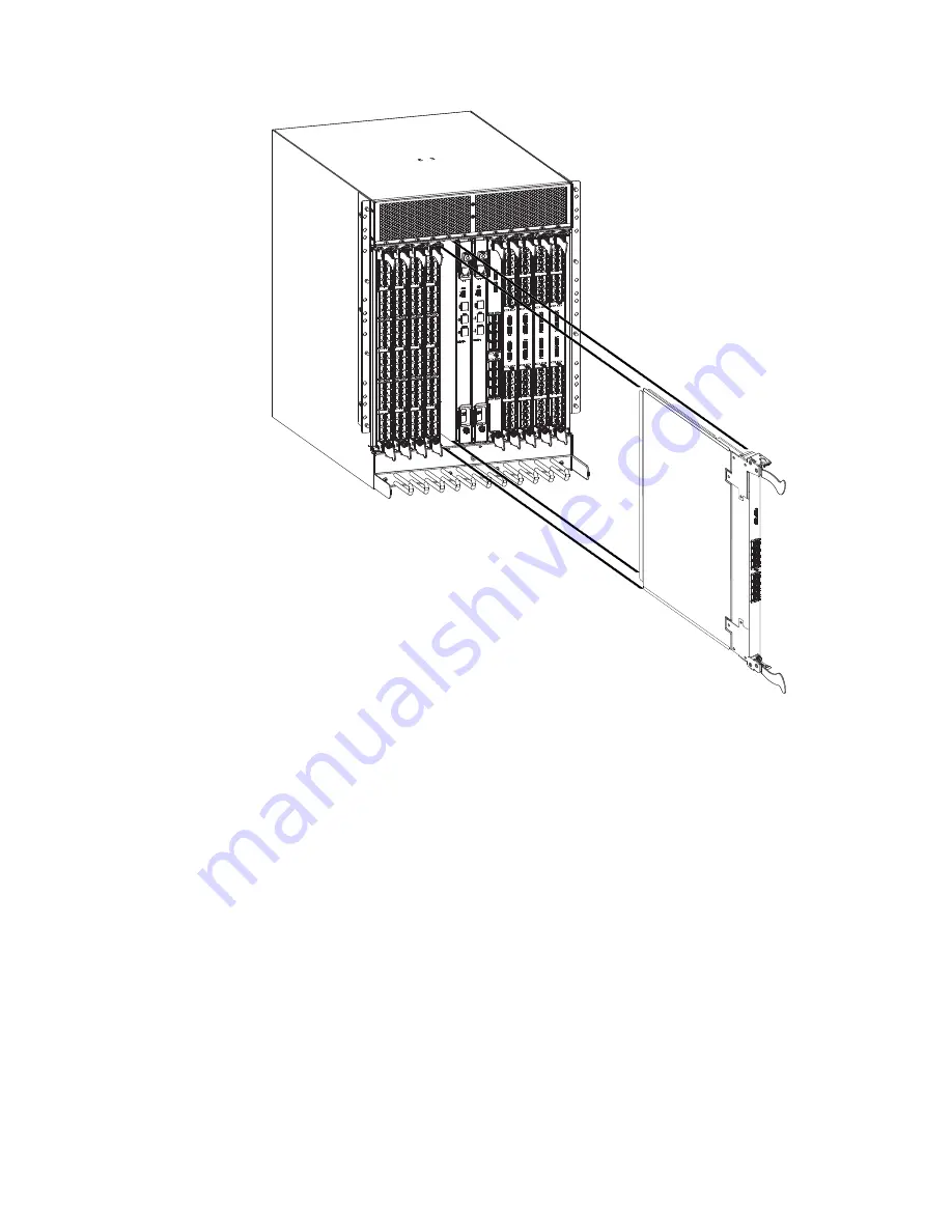
Installing a core switch blade (CR16-8)

Attention:

Follow ESD precautions (“ESD precautions” on page xix).

Note:

The CR16-8 blade is compatible only with the SAN768B-2.

Complete the following steps to install a CR16-8 core switch blade.

1.

Open the ejectors by rotating them toward the center of the blade face. Orient
the CR blade so that the handles are toward you and the flat metal side is on
your left.

2.

Align the flat side of the core switch blade inside the lower and upper blade
guides in the slot. Slide the core switch blade into the slot until it is firmly
seated.

3.

Close the ejectors by rotating them away from the center of the blade. The
levering action of the ejectors seats the blade in the slot.

4.

Power on the blade by screwing in the thumbscrews.

b768ig073

Figure 28. Removing the core switch blade

Chapter 5. Removing and installing components

85

Summary of Contents for SAN768B-2

Page 1: ...and User Guide Service information 2499 816 GA32 0893 00 Read Before Using This product contains software that is licensed under written license agreements Your use of such software is subject to the...

Page 2: ......

Page 3: ...IBM System Storage SAN768B 2 Installation Service and User Guide Service information 2499 816 GA32 0893 00...

Page 4: ...NESS MACHINES CORPORATION PROVIDES THIS PUBLICATION AS IS WITHOUT WARRANTY OF ANY KIND EITHER EXPRESS OR IMPLIED INCLUDING BUT NOT LIMITED TO THE IMPLIED WARRANTIES OF MERCHANTABILITY OR FITNESS FOR A...

Page 5: ...pportportal Search for the product Machine type or product name and then follow links for Downloads More detailed instructions are available through the Accessing firmware updates and OS documentation...

Page 6: ...tions for improving this document send us your comments by e mail to starpubs us ibm com Be sure to include the following v Exact publication title v Publication form number for example GC26 1234 02 v...

Page 7: ...20 Port numbering 26 Chassis slots 27 Cable organization 27 Removing a SAN768B 2 from the cabinet 29 Chapter 3 Starting and configuring the SAN768B 2 31 Providing power to the SAN768B 2 33 Establishin...

Page 8: ...97 Possible ICL configurations 98 Removing the batteries 100 Removing and replacing the chassis 101 Verifying necessity of replacement 102 Preparing for a chassis replacement 102 Disconnecting the SAN...

Page 9: ...ass A Electronic Emission Statement 148 Japan Voluntary Control Council for Interference VCCI Class A Statement 148 Japan Electronics and Information Technology Industries Association JEITA Statement...

Page 10: ...viii SAN768B 2 Installation Service and User Guide...

Page 11: ...r blade CP8 components 58 19 Core switch blade CR16 8 LEDs and QSFP connectors 60 20 Power supply LEDs 62 21 Blower assembly LEDs 63 22 LEDs on the WWN card and bezel 65 23 Chassis door 68 24 Cable ma...

Page 12: ...x SAN768B 2 Installation Service and User Guide...

Page 13: ...1 Messages that may indicate WWN card failure 64 12 WWN LED patterns 65 13 Steps for upgrading through multiple versions of Fabric OS 79 14 ICL connector port LEDs 96 15 Critical information checklist...

Page 14: ...xii SAN768B 2 Installation Service and User Guide...

Page 15: ...xamples of the danger caution and attention notices in the sections that follow v Note These notices provide important tips guidance or advice v Attention notices on page xix These notices indicate po...

Page 16: ...ace dangerous voltage on the metal shell If any of the conditions are not as described STOP Ensure the improper voltage or impedance conditions are corrected before proceeding D003 DANGER An electrica...

Page 17: ...ble use one hand only to connect or disconnect signal cables v Never turn on any equipment when there is evidence of fire water or structural damage v Disconnect the attached power cords telecommunica...

Page 18: ...t relocation or disposal 500 lbs 227 kg a69i0333 DANGER Heavy equipment personal injury or equipment damage might result if mishandled D006 Caution notices A caution notice calls attention to a situat...

Page 19: ...cal outlet to avoid electrical shock C018 CAUTION This product might contain one or more of the following devices CD ROM drive DVD ROM drive DVD RAM drive or laser module which are Class 1 laser produ...

Page 20: ...ER Hazardous voltage current or energy levels are present inside any component that has this label attached Do not open any cover or barrier that contains this label L001 DANGER Rack mounted devices a...

Page 21: ...re cable to a radius less than 5 cm 2 in you can damage the cable Tie wraps are not recommended for optical cables because they can be easily overtightened causing damage to the cable ESD precautions...

Page 22: ...to ensure that the outlet is correctly wired and grounded to prevent an electrical shock R001 part 1 of 2 CAUTION v Do not install a unit in a rack where the internal rack ambient temperatures will ex...

Page 23: ...Verify that the route that you choose can support the weight of the loaded rack cabinet Refer to the documentation that came with your rack cabinet for the weight of a loaded rack cabinet Verify that...

Page 24: ...er cable for damage 4 Check the external signal cable for damage 5 Check the cover for sharp edges damage or alterations that expose the internal parts of the device 6 Check that any unused serial por...

Page 25: ...ct for translated environmental statements and information regarding product recycling and disposal This document may be provided either in printed version or on a documentation CD See Removing the ba...

Page 26: ...xxiv SAN768B 2 Installation Service and User Guide...

Page 27: ...s product The documentation may be printed material on the documentation CD that is shipped with the product or available on the web through the IBM Support Portal or IBM Publications Center v IBM Sys...

Page 28: ...6 Brocade DCX 4S SAN384B 2499 Model 192 Brocade DCX SAN768B 2499 Model 384 Brocade Encryption Switch SAN32B E4 2498 Model E32 Brocade 8000 IBM Converged Switch B32 3758 Models B32 and L32 Brocade 7800...

Page 29: ...ontact the vendor for the accessibility information about its products Related accessibility information You can view the publications for the SAN768B 2 in Adobe Portable Document Format PDF using the...

Page 30: ...xxviii SAN768B 2 Installation Service and User Guide...

Page 31: ...amic growth and change providing high availability access to information and reducing infrastructure and administrative costs Key features of the SAN768B 2 include v Up to 384 16 Gbps external ports i...

Page 32: ...s only v Diagnostic port D_Port functionality v Fibre Channel over IP FCIP functionality through the FX8 24 blade Attention This product is not intended to be connected directly or indirectly by any m...

Page 33: ...cture v Modular hot swappable field replaceable units FRUs Three blower assemblies Up to four power supplies Two WWN cards Blades use small form factor pluggable SFP and mSFP optical transceivers SFP...

Page 34: ...agement comb 3 Control processor blade CP8 Figure 2 on page 5 shows a sample configuration of the non port side of the SAN768B 2 with 4 power supplies 1 2 3 4 5 b768ig062 Figure 1 Port side of the SAN...

Page 35: ...es available for the SAN768B 2 Description Feature Code Name Function Control processor blade N A CP8 The CP8 blade contains the control plane for the chassis There are two CP8 blades for redundancy T...

Page 36: ...ge server blade This core switch blade is compatible only with the SAN768B 2 32 port 16 Gbps port blade FC3632 FC16 32 A 32 port port blade supporting 2 4 8 10 and 16 Gbps Fibre Channel port speeds Th...

Page 37: ...ths v Fabric Shortest Path First FSPF rerouting around failed links v Integration with Simple Network Management Protocol SNMP managers v Automatic control processor failover v Nondisruptive hot softw...

Page 38: ...essor v USB port on control processor blades for most tasks that formerly required an FTP SCP server including software and firmware upgrades v Nonvolatile random access memory NVRAM containing the OE...

Page 39: ...ccess controls RBACs v Administrative domains Virtual fabrics v Boot PROM password reset v Password hardening policies v Upfront login in Web Tools v Login banner v Monitoring of attempted security br...

Page 40: ...eme The SAN768B 2 supports SNMPv1 and SNPMv3 When SNMP devices send SNMP messages to a management console running SAN management software the information is stored in a management information base MIB...

Page 41: ...N768B 2 One SAN768B 2 is installed in the cabinet at the factory If the SAN768B 2 is already installed in the cabinet continue on to Chapter 3 Starting and configuring the SAN768B 2 on page 31 Note So...

Page 42: ...ured at the blower inlet does not exceed 40 C 104 F during operation Ordering the lift tool Important The lift tool is required only when you install an additional SAN768B 2 or when you install or rem...

Page 43: ...he paperwork and components are packed and restored in the arbocrate shipping container of the lift tool Ensure that the lift tool is functioning properly before you release the tool to UPS Logistics...

Page 44: ...duct C015 Note A fully populated SAN768B 2 eight FC8 64 port cards 512 ports weighs approximately 159 2 kg 351 lb and requires the specified lift tool to install it Installing a SAN768B 2 in a cabinet...

Page 45: ...ession and configuring the SAN768B 2 domain ID date and time and additional system parameters Verifying and backing up the configuration 20 minutes Ethernet cable for Telnet access Refer to the Fabric...

Page 46: ...ration 1 C 10 32 x 5 8 inch 1 58 cm panhead Phillips screw washer 6 For cabinets that have vertical rails with round holes D 10 32 clip nut 6 E 1 4 20 x 1 2 in 1 27 cm panhead Phillips screw with lock...

Page 47: ...the accessory kit and the packing foam from the top of the chassis Set the kits aside for later use 3 Lift the cardboard box off the chassis and remove the plastic bag from around the chassis Save th...

Page 48: ...enough to allow the brackets to slide easily to adjust the length 3 Position the shelf brackets A and B with the adjustable ends at the intake aisle side of the cabinet see Figure 4 and attach them to...

Page 49: ...e 22 for approximate positions Note Do not align the clip or retainer nuts with the top or bottom holes of the SAN768B 2 mounting brackets because the door will interfere with the screw heads Removing...

Page 50: ...1 through step 9 on page 22 describe how to use the lift tool PN 09P2481 and the 24 inch load plate PN 11P4369 to install a SAN768B 2 in the cabinet Step 10 on page 22 through step 23 on page 24 descr...

Page 51: ...lift tool 2 Attach the 24 inch load plate to the lift tool 3 Although not required you can remove the power supplies and blower assemblies from the SAN768B 2 to reduce the weight This can reduce the w...

Page 52: ...AN768B 2 go to step 11 If you are installing the upper SAN768B 2 go to step 12 on page 23 11 For the lower SAN768B 2 install the bridge tool by completing the following steps a Remove the bridge tool...

Page 53: ...another 45 Make sure that the following conditions are met v The two pin section of the support is on the back of the vertical support v The one pin section is on the front of the vertical support No...

Page 54: ...s earlier Tighten the screws to a torque of 37 cm kg 32 in lb See Figure 9 for the approximate location of the screws Note Do not use the top or bottom holes of the SAN768B 2 mounting brackets because...

Page 55: ...b768ig032 Figure 10 Aligning the chassis door with the ball studs on the chassis Chapter 2 Installing and removing a SAN768B 2 25...

Page 56: ...ssis link connectors are numbered from 0 through 7 from bottom to top Each connector is actually a group of four 16 Gbps ports v FC16 32 port blade Ports are numbered from 0 through 15 from bottom to...

Page 57: ...5 8 9 10 11 Chassis slots Slots are numbered 1 through 12 from left to right when facing the port side of the SAN768B 2 Control processor blades CP8 can be installed only in slots 6 and 7 Core switch...

Page 58: ...tween optics in the new mSFP transceiver is smaller than in standard SFPs Patch cables and panels can be used to attach standard size cabling to the blade if necessary Figure 12 illustrates the mSFP t...

Page 59: ...mbled The assembly and disassembly instructions are included with the lift tool 2 Remove both power cords from the SAN768B 2 3 Optionally remove the power supplies and blower assemblies to reduce the...

Page 60: ...o ensure that they are locked into position c Raise the platform to allow enough room to attach the anti tip bracket d Secure the anti tip bars with the anti tip bracket and bolt 10 Move the lift tool...

Page 61: ...the following parameters v IP address and subnet mask for the chassis v IP addresses host names subnet masks and gateway addresses for both CP blades v Switch name v Domain ID for the SAN768B 2 option...

Page 62: ...etting the Domain ID on page 37 4 Verify the PID mode and connect the SAN768B 2 to the fabric See Verifying the PID mode on page 39 5 Enable software licenses See Determining installed software licens...

Page 63: ...and Attention To prevent a potential IP address conflict do not connect the SAN768B 2 to the network until the IP addresses are configured Note To power off the SAN768B 2 see Powering off the SAN768B...

Page 64: ...40 characters long They must begin with an alphabetic character They can include numeric characters the dot and the underscore _ Passwords are case sensitive and they are not displayed when you enter...

Page 65: ...23 123 123 120 Ethernet Subnetmask 0 0 0 0 123 123 123 123 Fibre Channel IP Address 0 0 0 0 Fibre Channel Subnetmask 0 0 0 0 Issuing gratuitous ARP Done Committing configuration Done swDir admin ipadd...

Page 66: ...procedures through a Telnet session log in to the SAN768B 2 by Telnet using the admin login The default password is password Customize a switch name The switch name of the SAN768B 2 can be up to 30 ch...

Page 67: ...troubleshooting they should be set correctly Setting the date To set the date follow these steps 1 If necessary log on to the SAN768B 2 by Telnet using the admin account The default password is passwo...

Page 68: ...t Synchronizing local time To synchronize the local time of the principal or primary switch with that of an external NTP server follow these steps 1 If necessary log on to the switch by Telnet using t...

Page 69: ...e example above the license key is AAbbccDDeeFFeeGG Keep a copy of the license key for reference The 64 bit chassis ID is required to obtain and activate licenses for the SAN768 2 The chassis ID is av...

Page 70: ...ide in easily ensure that it is correctly oriented 3 Repeat steps 1 and 2 for the remaining ports 4 Organize the cables as required For recommendations regarding cable management refer to Managing cab...

Page 71: ...lot Port QSFP Address Media Speed State Proto 256 3 0 0 id 16G No_SigDet FC 257 3 1 0 id 16G No_SigDet FC 258 3 2 0 id 16G No_SigDet FC 259 3 3 0 id 16G No_SigDet FC 260 3 4 1 16G No_Module FC 261 3 5...

Page 72: ...hed to the rack rails to organize the cables off to the side of the chassis and away from the chassis exhaust vents v Keep LEDs visible by routing port cables and other cables away from the LEDs For t...

Page 73: ...IBM SAN web page www ibm com systems storage san v Select the SAN768B 2 and SAN384B 2 product link v On the displayed product page click the Interoperability Matrix link in the Learn more section Fir...

Page 74: ...system using the sysShutdown command switch admin sysshutdown This command will shutdown the operating systems on your switch You are required to power cycle the switch in order to restore operation...

Page 75: ...zoning ON BB switchBeacon OFF FC Router ON FC Router BB Fabric ID 10 Address Mode 0 Index Slot Port Address Media Speed State Proto 0 1 0 780000 id N8 No_Light FC Disabled Switch not ready for EX_Por...

Page 76: ...le FC 44 3 12 782c00 id N8 No_Light FC 45 3 13 782d00 id N8 No_Light FC 46 3 14 782e00 N8 No_Module FC 47 3 15 782f00 N8 No_Light FC 165 3 21 78a500 N8 No_Module FC 166 3 22 78a600 id N8 No_Light FC 1...

Page 77: ...0 4 20 78b400 id N8 No_Light FC 181 4 21 78b500 id N8 No_Light FC 182 4 22 78b600 id N8 No_Light FC 183 4 23 78b700 id AN No_Sync FC 184 4 24 78b800 N16 No_Module FC 185 4 25 78b900 N16 No_Module FC 1...

Page 78: ...No_Module FC 1156 5 36 16G No_Module FC 1157 5 37 16G No_Module FC 1158 5 38 16G No_Module FC 1159 5 39 16G No_Module FC 1160 5 40 16G No_Module FC 1161 5 41 16G No_Module FC 1162 5 42 16G No_Module F...

Page 79: ...ture Day 14 Month 12 Year 2010 Update Day 28 Month 3 Year 2011 Time Alive 299 days Time Awake 0 days CP BLADE Slot 7 Header Version 2 Power Consume Factor 40 Factory Part Num 60 1000376 08 Factory Ser...

Page 80: ...2011 Time Alive 319 days Time Awake 0 days POWER SUPPLY Unit 3 Header Version 2 Power Consume Factor 2000 Factory Part Num 23 0000067 01 Factory Serial Num AGC2M44EKPL Manufacture Day 29 Month 12 Yea...

Page 81: ...s v Port or application blade status v Control processor blade CP8 status on page 57 v Core switch blade CR16 8 status on page 59 v Power supply status on page 61 v Blower assembly status on page 62 v...

Page 82: ...1 Power LED 3 Fibre Channel port 2 Status LED 4 Port status LED 2 1 3 4 b768ig064 Figure 14 FC16 32 port blade 52 SAN768B 2 Installation Service and User Guide...

Page 83: ...1 Power LED 3 Fibre Channel port 2 Status LED 4 Port status LED 2 1 3 4 b768ig065 Figure 15 FC16 48 port blade Chapter 4 Monitoring system components 53...

Page 84: ...LED 3 Fibre Channel port 2 Power LED 4 Port status LED Note The FC8 64 port blade requires narrower OM 3 LC cables 3 4 1 2 B768ig046 Figure 16 FC8 64 port blade 54 SAN768B 2 Installation Service and U...

Page 85: ...1 Power LED 4 GbE port 6 LED 7 Port map 2 Status LED 5 10 GbE port 0 3 GbE port 6 6 10 GbE port 0 LED 4 3 5 6 7 2 1 b768ig047 Figure 17 FX8 24 extension blade Chapter 4 Monitoring system components 55...

Page 86: ...e slider is pushed up and the ejectors are fully engaged Blade status LED No light LED is off Blade is either healthy or does not have power Verify that the power LED is on Steady amber Blade is fault...

Page 87: ...istentEnable command Reset the port from the workstation using the portEnable or portCfgPersistentEnable command Fast flashing amber on 1 2 second then off 1 2 second Transceiver or port is faulty Cha...

Page 88: ...onents 1 Power LED 5 Console port 10101 2 Status LED 6 Ethernet port MGMT IP 3 USB LED 7 Ethernet port SERVICE IP 4 USB port 8 Active CP LED 3 4 5 6 7 8 1 2 b768ig023 Figure 18 Control processor blade...

Page 89: ...ct it Ethernet link status No light LED is off Either an Ethernet link is not detected or it does not have incoming power Ensure the blade has power Ethernet cable is firmly seated and connected devic...

Page 90: ...witch blade and its components 1 Power LED 4 QSFP connectors 2 Status LED 5 QSFP connector status LEDs 3 QSFP port map and trunking diagram Table 8 CR16 8 blade LED descriptions LED purpose Color Stat...

Page 91: ...amber QSFP module is in all four ports have no signal no sync Ensure that the cable is properly connected If the LED remains amber contact IBM Blinking amber Port is disabled or faulted FC link activi...

Page 92: ...of a blower assembly 1 Check the LED indicators on the blower assembly see Figure 21 on page 63 The LED patterns may temporarily change during POST and other diagnostic tests for information about ho...

Page 93: ...or Status Recommended action Power No Light LED is off Blower assembly does not have power Ensure that the blower assembly is firmly seated and has power Steady green Blower assembly has power No acti...

Page 94: ...to determine the status of the WWN card 1 Enter the chassisShow command to display information about the WWN card WWN units correspond to information specific to the WWN card Error messages that may...

Page 95: ...rd is faulty Check card No light LED is off Card is OK No action required Note If a blade slot has a filler panel installed the corresponding LEDs on the WWN card do not light up Note If a status LED...

Page 96: ...66 SAN768B 2 Installation Service and User Guide...

Page 97: ...and installing a power supply on page 86 v Removing and installing a blower assembly on page 88 v Removing and installing a WWN bezel and WWN card on page 89 v Removing and installing transceivers on...

Page 98: ...SAN768B 2 can continue to operate during the replacement of the cable management comb Time and items required The replacement procedure for the cable management comb takes less than 5 minutes A 1 Phil...

Page 99: ...and tighten the four screws to secure the cable management comb to the chassis 3 Arrange the cables along the cable management comb 4 Replace the chassis door Removing and installing port and applicat...

Page 100: ...is door see Removing and installing the chassis door on page 67 2 A failed port or application blade can be identified by inspecting the LEDs on the front panel of each blade Check the power LED statu...

Page 101: ...oving the blade 10 Open the ejectors by pulling them toward the center of the blade face Pull the blade out of the chassis using the ejectors Figure 25 11 If the blade is not being replaced by another...

Page 102: ...Install the transceivers and cables in the blade For mSFP transceivers FC8 64 port blade only it is recommended that you install the cables in the transceivers before installing the transceivers in th...

Page 103: ...This section describes how to remove and install a control processor CP8 blade Each SAN768B 2 has two CP8 blades located in slot 6 and slot 7 Attention The firmware upgrade policy for CP8 blades spec...

Page 104: ...processor CP8 blade Attention If you are upgrading through multiple versions of the Fabric OS refer to Table 13 on page 79 to see which intermediate versions of the Fabric OS you will need Plan carefu...

Page 105: ...ve CP blade and run the following steps a Run the haFailover command to make the standby CP blade the active blade The currently active CP blade becomes the standby blade Wait until the status LED on...

Page 106: ...Failover command Wait until the failover has completed Use the haShow command to verify the CPs are synchronized and the failover is complete Depending on the nature of the CP failure it is possible t...

Page 107: ...information about determining the version of firmware on the replacement CP blade and upgrading it if necessary Attention Follow ESD precautions see ESD precautions on page xix whenever handling a bl...

Page 108: ...up to the version on the active CP blade which must be at least 7 0 0 3 If the firmware versions for both CP blades are the same skip to Completing the CP8 blade replacement on page 83 If the firmware...

Page 109: ...system settings for firmwaredownload System settings check passed You are running firmwaredownload with auto reboot disabled After firmware is downloaded please reboot the system to activate the new f...

Page 110: ...rsions 5 On the standby CP blade the blade for which you just changed the firmware level run reboot The reboot of the standby CP will initiate a firmwarecommit to the secondary partition and log you o...

Page 111: ...blade AS admin if you are not still logged in and enter usbStorage e to enable the USB device 4 Remove the serial cable from the active CP blade and attach it to the standby CP blade and log in as adm...

Page 112: ...s 7 Ensure that you are still logged in to the standby CP blade the blade for which you just changed the firmware level and type reboot The reboot of the standby CP will initiate a firmwarecommit to t...

Page 113: ...er firmwareShow to verify that the firmware version has been updated and that the versions are the same on the two CP blades Not all slot numbers are shown in this example SAN768B 2_a admin firmwaresh...

Page 114: ...messages Generic system driver messages FABSYS Platform system driver messages Platform Error messages that indicate a problem with a core switch blade Function fail messages for the core switch blade...

Page 115: ...at the handles are toward you and the flat metal side is on your left 2 Align the flat side of the core switch blade inside the lower and upper blade guides in the slot Slide the core switch blade int...

Page 116: ...d install a power supply Attention Depending on the blade configuration of the chassis and the number of power supplies installed the SAN768B 2 may be able to continue operating during the replacement...

Page 117: ...supply from the chassis supporting the power supply from beneath as you remove it see Figure 30 6 If you are not replacing the power supply insert a filler panel into the slot Installing a power supp...

Page 118: ...bly Time and items required The installation procedure for each blower assembly takes less than 5 minutes The following items are required for the blower assembly installation v Replacement blower ass...

Page 119: ...a WWN bezel and WWN card Note The World Wide Name WWN cards contain fully redundant circuits and normally do not require installation Two WWN cards are located beneath the WWN bezel Time and items re...

Page 120: ...ctive CP Run the haShow command to determine the active CP 3 Run the supportSave command on the active CP to capture all settings If any problems occur during the replacement the information will be i...

Page 121: ...l and WWN card Attention Follow ESD precautions 1 Unpack the new WWN card and save the packaging for the faulty WWN card 2 Hold the card by the edges and insert the WWN cable onto the WWN module until...

Page 122: ...IBM SAN web page www ibm com systems storage san v Select the IBM System Storage SAN768B 2 and SAN384B 2 product link v On the displayed product page click the Interoperability Matrix link in the Lea...

Page 123: ...34 Detach the cable from the 16 Gbps SFP once you have disconnected the unit from the port See the mSFP transceiver in Figure 36 on page 95 for the basic appearance of the 16 Gbps transceiver Complete...

Page 124: ...on a cable so that the key the ridge on one side of the cable connector is aligned with the slot in the transceiver Insert the cable into the transceiver until the latching mechanism clicks Cables are...

Page 125: ...mechanism clicks 2 Position the optical transceiver so that the key is oriented correctly to the port Insert the transceiver into the port until it is firmly seated and the latching mechanism clicks...

Page 126: ...n QSFP cable insertion and confirmation Check for console messages or wait for all four ports to come online Steady green Both ends of QSFP cable are in and all ports are online Fulll link is establis...

Page 127: ...nsceiver by rotating the bail down and using the bail to pull the transceiver out of the connector on the blade 5 Repeat for each cable that requires replacement 6 If you are not replacing the ICL cab...

Page 128: ...ing the chassis door on page 67 5 Once all the cables are attached see the Fabric OS Administrator s Guide for the configuration procedure Possible ICL configurations The following figure illustrates...

Page 129: ...1 Chassis 1 2 Chassis 2 1 2 384b083 Figure 38 QSFP cable connections sample configuration parallel type Chapter 5 Removing and installing components 99...

Page 130: ...egulations In the United States IBM has a process for the collection of this battery For information call 1 800 426 4333 Have the IBM part number for the battery unit available when you call C003 1 Re...

Page 131: ...4 R52 R50 R48 R46 R44 R42 R40 R38 R36 R34 C28 C29 R152 R385 R316 R168 R437 R364 R438 R386 R363 R384 C32 C31 C34 C33 C67 C68 C66 C69 R158 R377 R381 R376 R378 R380 R375 R170 R373 R374 R365 R372 R171 R17...

Page 132: ...ffening rail v The psShow or fanShow commands continue to show a faulty component even though the component has been replaced v The slotShow command continues to show a faulty processor core switch or...

Page 133: ...s New factory serial number New serial number if available Complete the following steps to record critical switch and SAN information 1 Open a Telnet session and login to the SAN768B 2 as admin The de...

Page 134: ...er chassisShow then copy the command output into the config miscinfo txt file Factory Serial Num and Serial Num are listed under Chassis WWN Unit 1 If the current WWN cards are the original cards the...

Page 135: ...ed to the fabric switch admin supportshow version 7 0 0 output truncated switch admin 9 Record the cable connections between the SAN768B 2 and the target devices and ports See Cable routing tables on...

Page 136: ...listed below Refer to the instructions in Chapter 5 Removing and installing components on page 67 for component specific removal instructions 1 Remove the cable management comb as described in Removin...

Page 137: ...any of the components If the component does not slide in easily ensure that it is correctly aligned and positioned before continuing Attention Do not turn on the power until it is time to verify hard...

Page 138: ...anual Complete the following steps to download the configuration 1 Log in to the chassis as admin switch admin login login admin password xxxxxxxx switch admin Note If you are using the Virtual Fabric...

Page 139: ...Slot Port Address Media Speed State Proto 0 1 0 500000 4G No_Module FC 1 1 1 500100 4G No_Module FC 2 1 2 500200 4G No_Module FC 3 1 3 500300 4G No_Module FC 4 1 4 500400 4G No_Module output truncated...

Page 140: ...he Fabric OS Administrator s Guide a Install a transceiver into each port if not already installed see Removing and installing transceivers on page 92 b Select the cable that corresponds to the port a...

Page 141: ...bs Port 0 1 2 3 4 5 6 7 8 9 FID 1 1 1 1 1 128 128 128 128 128 output truncated switch admin 2 Determine any differences between the information in the SANafter txt file and the information in the SAN...

Page 142: ...Switch end Device end Slot 1 Port 0 North 24 1 0 East 26 0 SANB32 East 26 0 Slot 5 Serial North 24 5 Serial Work 5 2 Workstation 5 Com 2 Slot 8 Port 15 North 24 8 15 RAID 16 4 RAID 16 4 Table 17 Cable...

Page 143: ...continued Slot Port Cable labels Connected device Slot Port of device Slot Port Switch end Device end 29 30 31 32 33 34 35 36 37 38 39 40 41 42 43 44 45 46 47 48 49 50 51 52 53 54 55 56 57 58 59 60 6...

Page 144: ...114 SAN768B 2 Installation Service and User Guide...

Page 145: ...for all procedures in this section to avoid damaging the port blades or chassis v Wear a grounded ESD strap when handling a port blade see ESD precautions on page xix v Carefully remove the protectiv...

Page 146: ...e the filler panel or port blade Refer to Removing a blade on page 70 or Removing a filler panel on page 72 Attention A filler panel should be removed only when being replaced with a port blade or new...

Page 147: ...due to port and cable density Items required v ESD electrostatic discharge grounding strap v Workstation computer v Port blade v Phillips screwdriver v mSFP transceivers as needed v OM 3 LC optical ca...

Page 148: ...wer OM 3 LC cables are used to connect the FC8 64 These cables are offered by several major manufacturers Contact your IBM representative for options regarding different cable and patch panel configur...

Page 149: ...Workstation computer v Port blade v Phillips screwdriver v Transceivers as needed v Optical cables as needed Procedures Follow the links in the steps below to complete this installation 1 Remove the c...

Page 150: ...talling the chassis door on page 67 FC7871 Installing a QSFP and inter chassis license This feature can be installed while the SAN768B 2 is operational Time required Less than 10 minutes not including...

Page 151: ...the inter chassis links See the iclCfg section in the Fabric OS Command Reference Manual for CLI command options 9 Verify the operation of the ICL see Table 14 on page 96 10 Refer to the Fabric OS Adm...

Page 152: ...122 SAN768B 2 Installation Service and User Guide...

Page 153: ...tocol FC PH Fibre Channel Physical and Signalling Interface standard Classes of service Class 2 Class 3 Class F interswitch frames Fabric initialization Complies with FC SW 5 0 FC IP IP over Fibre Cha...

Page 154: ...routing For the FX8 24 blade FC to FC 2 1 msec any port to any port at 8 Gbps cut through routing Maximum frame size 2112 byte payload Frame buffers 8000 per ASIC with 5000 more that can be borrowed f...

Page 155: ...Performance monitoring Extended Fabrics Fabric Watch FDMI Frame Redirection FSPF Integrated Routing IPFC ISL Trunking Management Server N_Port Trunking NPIV NTP v3 Port Fencing Registered State Change...

Page 156: ...ies v No fan assemblies 37 3 kg 82 2 lb Table 21 lists the weights of the compatible blades and FRUs Table 21 System FRU weights FRU Weight CP blade CP8 3 0 kg 6 6 lb CR blade CR16 8 3 7 kg 8 1 lb FC1...

Page 157: ...0 watt 48V dc bulk power supplies Bulk power supplies produce the intermediate distribution voltage in the distributed power system The power specifications listed in Table 22 are calculated for fully...

Page 158: ...lf sine wave 33G 11ms duration half sine wave Vibration 0 5G p p 5 500 Hz at 1 0 octave minute 2 0G p p 5 500 Hz at 1 0 octave minute Air flow 595 cu m hr 350 cu ft min None required Heat dissipation...

Page 159: ...229 ft 150 m 492 ft 380 m 1264 ft 400 m 1312 ft N A mSFP SFP 8 Gbps 21 m 68 ft 50 m 164 ft 150 m 492 ft 190 m 623 ft N A SFP 10 Gbps 33 m 108 ft 82 m 269 ft 300 m 984 ft 550 m 1804 ft N A mSFP SFP 16...

Page 160: ...you must also order the country specific power cords Contact your IBM representative for more information on these power cords 130 SAN768B 2 Installation Service and User Guide...

Page 161: ...ts depending on licensing and subsequent configuration of GbE port mode If operating in 10GbE mode the other end of the circuit must also be an FX8 24 operating in either 10GbE mode or dual mode with...

Page 162: ...e used over the FCIP link Fabrics connected through FCIP merge if the ports are configured as VE_Ports and do not merge if they are configured as VEX_Ports If VE_Ports are used in a Fibre Channel Rout...

Page 163: ...or logs refer to the Fabric OS System Error Messages Reference Manual and the Fabric OS Administrator s Guide for more information v Review RASlog entries v Enter the sensorShow command to determine t...

Page 164: ...he standby CP blade POST The system automatically performs POST each time it is powered on or reset To verify that POST has completed without error v Verify that all LEDs return to a normal state afte...

Page 165: ...uires maintenance Each diagnostic test can be implemented by entering the related command through a Telnet or serial session For a list of diagnostic tests and commands refer to the Fabric OS Administ...

Page 166: ...P Ethernet link speed negotiation set up by the network Specify the CP Ethernet link speed by entering the ifModeSet command Configuration data is inaccurate or cannot be accessed Chassis was powered...

Page 167: ...g shut down the port blades as necessary to return the temperature readings to the operating ranges Blades might be faulty Enter the slotShow command to determine status For more information enter the...

Page 168: ...138 SAN768B 2 Installation Service and User Guide...

Page 169: ...26 for details on the port numbering pattern for the different blades v Figure 40 shows an FC16 32 port blade v Figure 41 on page 140 shows an FC16 48 port blade v Figure 42 on page 141 shows an FC8...

Page 170: ...m to top 2 Status LED 4 FC ports 0 15 bottom to top 1 Power LED 3 FC ports 24 47 bottom to top 2 Status LED 4 FC ports 0 23 bottom to top 2 3 1 4 b768ig072 Figure 41 FC16 48 port blade 140 SAN768B 2 I...

Page 171: ...5 Port 61 LED 2 Status LED 6 Port 29 LED 3 Port 63 7 FC ports 32 63 bottom to top 4 Port 30 8 FC ports 0 31 bottom to top 8 7 3 2 1 5 6 4 b768ig057 Figure 42 FC8 64 port blade Appendix D Blade port n...

Page 172: ...C ports 6 11 numbered bottom to top 3 1 GbE ports 0 3 numbered bottom to top 7 1 GbE ports 4 9 numbered bottom to top 4 10 GbE ports 0 1 numbered bottom to top 3 4 5 6 7 1 2 b768ig034 Figure 43 FX8 24...

Page 173: ...cal law INTERNATIONAL BUSINESS MACHINES CORPORATION PROVIDES THIS PUBLICATION AS IS WITHOUT WARRANTY OF ANY KIND EITHER EXPRESS OR IMPLIED INCLUDING BUT NOT LIMITED TO THE IMPLIED WARRANTIES OF NON IN...

Page 174: ...roducts was obtained from the suppliers of those products their published announcements or other publicly available sources IBM has not tested those products and cannot confirm the accuracy of perform...

Page 175: ...s of Adobe Systems Incorporated in the United States and or other countries Java and all Java based trademarks and logos are trademarks of Sun Microsystems Inc in the United States other countries or...

Page 176: ...ed changes or modifications could void the user s authority to operate the equipment This device complies with Part 15 of the FCC Rules Operation is subject to the following two conditions 1 this devi...

Page 177: ...folgendem Warnhinweis versehen werden Warnung Dieses ist eine Einrichtung der Klasse A Diese Einrichtung kann im Wohnbereich Funk St rungen verursachen in diesem Fall kann vom Betreiber verlangt werd...

Page 178: ...the user may be required to take corrective actions Japan Electronics and Information Technology Industries Association JEITA Statement Japanese Electronics and Information Technology Industries Asso...

Page 179: ...Statement Australia and New Zealand Class A Statement Attention This is a Class A product In a domestic environment this product might cause radio interference in which case the user might be require...

Page 180: ...150 SAN768B 2 Installation Service and User Guide...

Page 181: ...ng need 102 chassis installing components 107 chassis replacing 101 comments sending iv components installing 67 removing 67 configuration backing up 42 parameters 33 configuration file backup 42 uplo...

Page 182: ...lade 71 FC3890 119 FC8 64 69 FC8 64 blade 71 filler panel 72 firmware 43 FX8 24 69 FX8 24 blade 71 119 inter chassis link ICL cable 97 mSFP 92 mSFPs 39 port blade 72 115 117 power supply 86 QSFP inter...

Page 183: ...filler panel 72 FS8 18 blade 70 FX8 24 69 FX8 24 blade 70 inter chassis link QSFP cable 95 97 mSFP 92 port blade 72 power supply 86 SAN768B 2 11 29 SFP 92 WWN bezel and card 89 removing components 67...

Page 184: ...transmission range multi mode media 129 OM1 129 OM2 129 OM3 129 OM4 129 SFP types 129 single mode media 129 transceiver 129 trunking port groups 40 V verifying chassis replacement need 102 CP8 blade 7...

Page 185: ......

Page 186: ...Part Number 99Y0730 Printed in USA GA32 0893 00 1P P N 99Y0730...

Reviews: