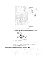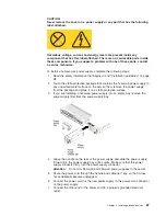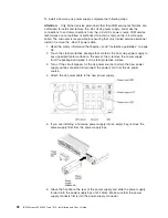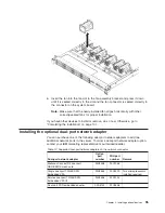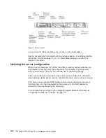
7. Route the power cord through the handle and cable tie if any, so that it does
not accidentally become unplugged.
8. Connect the power cord for the new power supply to the power-cord connector
on the power supply.
9. Connect the other ends of the dc power cable to the dc power source. Cut the
wires to the correct length, but do not cut them shorter than 150 mm (6 inch).
If the power source requires ring terminals, you must use a crimping tool to
install the ring terminals to the power cord wires. The ring terminals must be
UL approved and must accommodate the wires that are described in note 89.
The minimum nominal thread diameter of a pillar or stud type of terminal must
be 4 mm; for a screw type of terminal the diameter must be 5.0 mm.
10. Turn on the circuit breaker for the dc power source to which the new power
supply is connected.
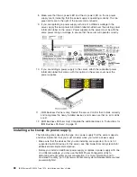
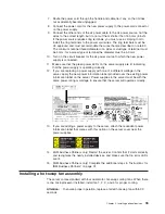
11. Make sure that the green power LEDs on the power supply are lit, indicating
that the power supply is operating correctly.
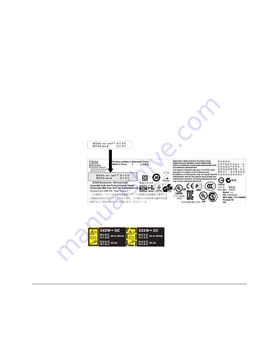
12. If you are replacing a power supply with one of a different wattage in the
server, apply the new power information label provided over the existing power
information label on the server. Power supplies in the server must be with the
same power rating or wattage to ensure that the server will operate correctly.
13. If you are adding a power supply to the server, attach the redundant power
information label that comes with this option on the server cover near the
power supplies.
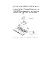
14. (IBM Business Partners only) Restart the server. Confirm that it starts correctly
and recognizes the newly installed devices, and make sure that no error LEDs
are lit.
15. (IBM Business Partners only) Complete the additional steps in “Instructions for
IBM Business Partners” on page 31.
Installing a hot-swap fan assembly
The server comes standard with four dual-motor hot-swap cooling fans. When there
is one microprocessor installed, install fan 1, 2, 3, and 5 for proper cooling.
Attention:
To ensure proper operation, replace a failed hot-swap fan within 30
seconds.
Chapter 2. Installing optional devices
93
Summary of Contents for Redboks System x3550 M4
Page 1: ...IBM System x3550 M4 Type 7914 Installation and User s Guide...
Page 2: ......
Page 3: ...IBM System x3550 M4 Type 7914 Installation and User s Guide...
Page 8: ...vi IBM System x3550 M4 Type 7914 Installation and User s Guide...
Page 46: ...30 IBM System x3550 M4 Type 7914 Installation and User s Guide...
Page 58: ...42 IBM System x3550 M4 Type 7914 Installation and User s Guide...
Page 88: ...72 IBM System x3550 M4 Type 7914 Installation and User s Guide...
Page 138: ...122 IBM System x3550 M4 Type 7914 Installation and User s Guide...
Page 142: ...126 IBM System x3550 M4 Type 7914 Installation and User s Guide...
Page 150: ...134 IBM System x3550 M4 Type 7914 Installation and User s Guide...
Page 156: ...140 IBM System x3550 M4 Type 7914 Installation and User s Guide...
Page 157: ......
Page 158: ...Part Number 00V9702 Printed in USA 1P P N 00V9702...

