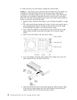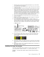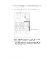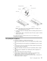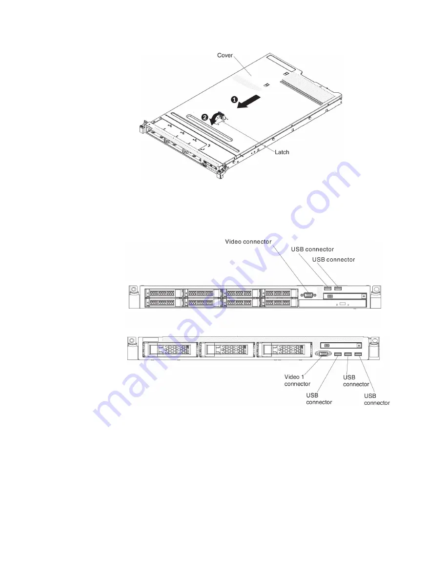
6. Slide the server all the way into the rack until it latches.
Connecting the cables
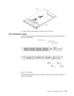
The following illustrations show the locations of the input and output connectors on
the front of the server.
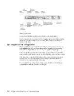
The following illustration shows the locations of the input and output connectors on
the rear of the server.
Figure 3. Front of server
Chapter 2. Installing optional devices
103
Summary of Contents for Redboks System x3550 M4
Page 1: ...IBM System x3550 M4 Type 7914 Installation and User s Guide...
Page 2: ......
Page 3: ...IBM System x3550 M4 Type 7914 Installation and User s Guide...
Page 8: ...vi IBM System x3550 M4 Type 7914 Installation and User s Guide...
Page 46: ...30 IBM System x3550 M4 Type 7914 Installation and User s Guide...
Page 58: ...42 IBM System x3550 M4 Type 7914 Installation and User s Guide...
Page 88: ...72 IBM System x3550 M4 Type 7914 Installation and User s Guide...
Page 138: ...122 IBM System x3550 M4 Type 7914 Installation and User s Guide...
Page 142: ...126 IBM System x3550 M4 Type 7914 Installation and User s Guide...
Page 150: ...134 IBM System x3550 M4 Type 7914 Installation and User s Guide...
Page 156: ...140 IBM System x3550 M4 Type 7914 Installation and User s Guide...
Page 157: ......
Page 158: ...Part Number 00V9702 Printed in USA 1P P N 00V9702...

