v
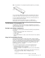
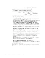
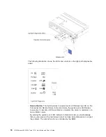
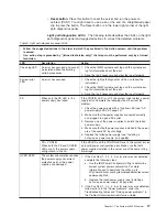
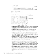
Reset button:
Press this button to reset the server and run the power-on
self-test (POST). You might have to use a pen or the end of a straightened paper
clip to press the button. The Reset button is in the lower-right corner of the light
path diagnostics panel.
Light path diagnostics LEDs:
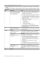
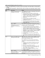
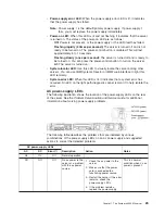
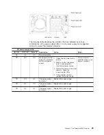
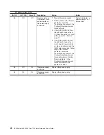
The following table describes the LEDs on the light
path diagnostics panel and suggested actions to correct the detected problems.
Table 2. Light path diagnostics panel LEDs
v
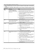
Follow the suggested actions in the order in which they are listed in the Action column until the problem
is solved.
v
If an action step is preceded by "(trained technician only)," that step must be performed only by a trained
technician.
LED
Description
Action
Check log LED
An error has occurred and cannot
be isolated without performing
certain procedures.
1. Check the IMM2 system event log and the system-error
log for information about the error.
2. Save the log if necessary and clear the log afterwards.
System-error
LED
An error has occurred.
1. Check the light path diagnostics LEDs and follow the
instructions.
2. Check the IMM2 system event log and the system-error
log for information about the error.
3. Save the log if necessary and clear the log afterwards.
PS
When only the PS LED is lit, a
power supply has failed.
If the CONFIG LED is not lit, the system might detect a power
supply error. Complete the following steps to correct the
problem:
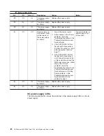
1. Check the power-supply with a lit yellow LED (see “AC
power-supply LEDs” on page 23).
2. Make sure that the power supplies are seated correctly
and plugged in a good AC outlet.
3. Remove one of the power supplies to isolate the failed
power supply.
4. Make sure that both power supplies installed in the server
are of the same AC input voltage.
5. Replace the failed power supply (see “Installing a
hot-swap ac power supply” on page 86).
PS + CONFIG
When both the PS and CONFIG
LEDs are lit, the power supply
configuration is invalid.
If the PS LED and the CONFIG LED are lit, the system issues
an invalid power configuration error. Make sure that both
power supplies installed in the server are of the same rating
or wattage.
OVER SPEC
The system consumption reaches
the power supply over-current
protection point or the power
supplies are damaged.
1. If the Pwr Rail (1, 2, 3, 4, 5, or 6) error was not detected,
complete the following steps:
a. Use the IBM Power Configurator utility to determine
current system power consumption. For more
information and to download the utility, go to
http://www-03.ibm.com/systems/bladecenter/resources/
powerconfig.html.
b. Replace the failed power supply (see “Installing a
hot-swap ac power supply” on page 86).
2. If the Pwr Rail (1, 2, 3, 4, 5, or 6) error was also detected,
follow actions in the "Power problems" under the
Troubleshooting tables and "Solving power problems" in
the
Problem Determination and Service Guide
.
Chapter 1. The System x3550 M4 server
17
Summary of Contents for Redboks System x3550 M4
Page 1: ...IBM System x3550 M4 Type 7914 Installation and User s Guide...
Page 2: ......
Page 3: ...IBM System x3550 M4 Type 7914 Installation and User s Guide...
Page 8: ...vi IBM System x3550 M4 Type 7914 Installation and User s Guide...
Page 46: ...30 IBM System x3550 M4 Type 7914 Installation and User s Guide...
Page 58: ...42 IBM System x3550 M4 Type 7914 Installation and User s Guide...
Page 88: ...72 IBM System x3550 M4 Type 7914 Installation and User s Guide...
Page 138: ...122 IBM System x3550 M4 Type 7914 Installation and User s Guide...
Page 142: ...126 IBM System x3550 M4 Type 7914 Installation and User s Guide...
Page 150: ...134 IBM System x3550 M4 Type 7914 Installation and User s Guide...
Page 156: ...140 IBM System x3550 M4 Type 7914 Installation and User s Guide...
Page 157: ......
Page 158: ...Part Number 00V9702 Printed in USA 1P P N 00V9702...

