v
Reset button:
Press this button to reset the server and run the power-on
self-test (POST). You might have to use a pen or the end of a straightened paper
clip to press the button.
v
Power-on LED:
When this LED is lit and not flashing, it indicates that the server
is turned on. When this LED is flashing, it indicates that the server is turned off
and still connected to an ac power source. When this LED is off, it indicates that
ac power is not present, or the power supply or the LED itself has failed.
Notes:
1. If this LED is off, it does not mean that there is no electrical power in the
server. The LED might be burned out. To remove all electrical power from the
server, you must disconnect the power cord from the electrical outlet.
2. The ac power and dc power LEDs are on the power supply and can be
viewed from the rear of the server. For additional information, see “Rear
view.”
v
Hard disk drive activity LED:
When this LED is lit, it indicates that either of the
hard disk drives is in use.
v
System locator LED:
This LED can be lit remotely by the system administrator
to aid in visually locating the server. If the server supports IBM Director, you can
use IBM Director to light this LED remotely. A system locator LED is also on the
rear of the server.
v
System-error LED (!):
When this LED is lit, it indicates that a system error has
occurred. An LED near the failing component on the system board is also lit to
help isolate the error.
v
USB connectors:
Connect a USB device to either of these connectors.
Notes:
1. If you want to attach a keyboard or mouse to this server, you must use a USB
keyboard or a USB mouse. For detailed information about the USB keyboard
and how to connect it to your server, see the documentation that comes with the
USB keyboard.
2. The server supports keyboardless operation. If a USB keyboard is not
connected to the server, when the server is turned on or restarted, error
message 301 will be displayed during POST. No action is required. POST will
continue within 1 minute.
3. If you want to attach a diskette drive to this server, you must use an external
USB diskette drive.
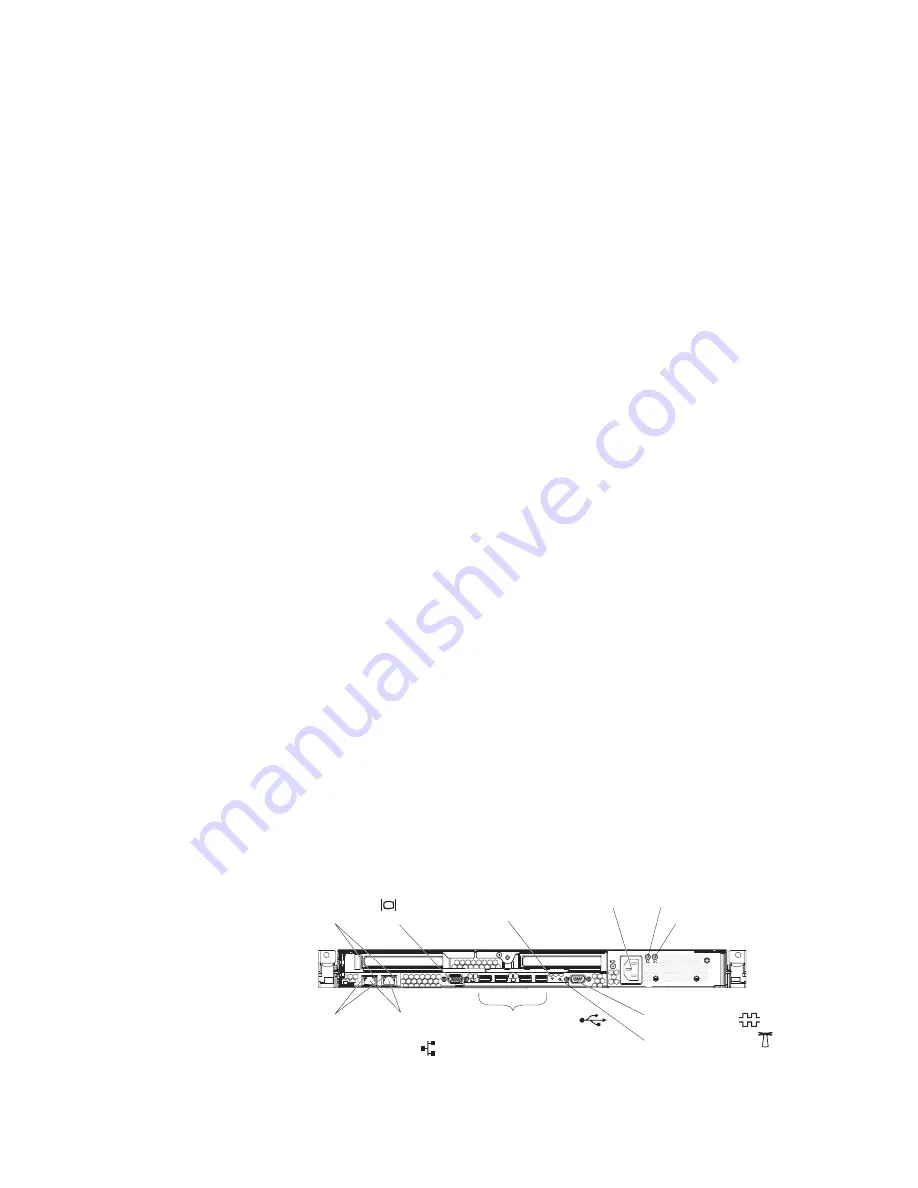
Rear view
The following illustration shows the connectors, switches, and LEDs on the rear of
the server.
USB connectors (4)
Ethernet
connectors
(2)
LAN activity LED
Link LED
Video
connector
Power-cord
connector
Serial connector
AC power LED
DC power LED
System locator LED
NMI switch
6
IBM System x3455 Type 7940 and 7941: Problem Determination and Service Guide
Summary of Contents for 7940
Page 1: ...IBM System x3455 Type 7940 and 7941 Problem Determination and Service Guide ...
Page 2: ......
Page 3: ...IBM System x3455 Type 7940 and 7941 Problem Determination and Service Guide ...
Page 8: ...vi IBM System x3455 Type 7940 and 7941 Problem Determination and Service Guide ...
Page 18: ...xvi IBM System x3455 Type 7940 and 7941 Problem Determination and Service Guide ...
Page 32: ...14 IBM System x3455 Type 7940 and 7941 Problem Determination and Service Guide ...
Page 36: ...18 IBM System x3455 Type 7940 and 7941 Problem Determination and Service Guide ...
Page 46: ...28 IBM System x3455 Type 7940 and 7941 Problem Determination and Service Guide ...
Page 142: ...124 IBM System x3455 Type 7940 and 7941 Problem Determination and Service Guide ...
Page 152: ...134 IBM System x3455 Type 7940 and 7941 Problem Determination and Service Guide ...
Page 158: ...140 IBM System x3455 Type 7940 and 7941 Problem Determination and Service Guide ...
Page 159: ......
Page 160: ... Part Number 49Y0088 Printed in USA 1P P N 49Y0088 ...


