background image

IDS2000 Dual-Row Aisle Containment 
Installation Guide (Split-type Skylight, Old-Version 
Sliding Door) 

3 Installation Scenarios in Dual Row Aisle Containment 


Issue 02 (2015-06-30) 

Huawei Proprietary and Confidential                                     

Copyright © Huawei Technologies Co., Ltd. 

37 


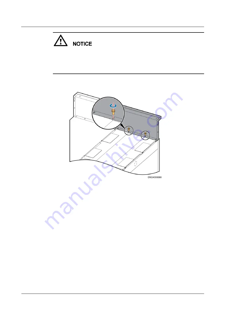
When securing the skylight connective plate to the cabinet, partially tighten the screws so 
that you do not have to remove the screws if the skylight cannot be accurately mounted. 
Fully tighten the screws after the skylight is accurately mounted. 


Align the center of the skylight connective plate with the cabinet center. The plate surface 
and the front beam of the cabinet should be on the same level. 

Figure 3-8


Installing a skylight connective plate at the top of air conditioner or UPS 

cabinets 


2.


Secure the adjacent skylight connective plates using M6 screws and nuts, as shown in 

Figure 3-9

. 

Summary of Contents for IDS2000 Dual-Row Aisle Containment

Page 1: ...IDS2000 Dual Row Aisle Containment V200R002 Installation Guide Split type Skylight Old Version Sliding Door Issue 02 Date 2015 06 30 HUAWEI TECHNOLOGIES CO LTD ...

Page 2: ... Huawei and the customer All or part of the products services and features described in this document may not be within the purchase scope or the usage scope Unless otherwise specified in the contract all statements information and recommendations in this document are provided AS IS without warranties guarantees or representations of any kind either express or implied The information in this docum...

Page 3: ... that may be found in this document are defined as follows Symbol Description Indicates an imminently hazardous situation which if not avoided will result in death or serious injury Indicates a potentially hazardous situation which if not avoided could result in death or serious injury Indicates a potentially hazardous situation which if not avoided may result in minor or moderate injury Indicates...

Page 4: ...ologies Co Ltd iii Symbol Description injury equipment damage and environment deterioration Change History Changes between document issues are cumulative The latest document issue contains all the changes made in earlier issues Issue 02 2015 06 30 Updated the skylight sliding door and cross pillar aisle containment installation methods Issue 01 2014 12 20 This issue is the first official release ...

Page 5: ...2 4 Combining Cabinets 20 2 4 1 Combining Server Cabinets 20 2 4 2 Combining Air Conditioners 21 2 5 Installing Cabinet Accessories 28 2 5 1 Installing Cabinet Sealing Plates 28 2 5 2 Removing Rack Power Distribution Unit 29 3 Installation Scenarios in Dual Row Aisle Containment 31 3 1 Installation Flowchart 31 3 2 Installing Skylights 31 3 3 Installing Cabinet Sealing Plates 45 3 4 Installing End...

Page 6: ...r 100 6 5 Installing End Panels for Cable Troughs 100 7 Installing the Access Control System 102 7 1 Installing Magnetic Locks and Magnets 103 7 2 Installing a Card Reader 109 7 3 Installing an Access Control Box 112 7 4 Installing Switches 115 8 Optional Installing the Lighting System 119 8 1 Installing Aisle Lights 119 8 2 Installing an In cabinet Light 123 9 Installing Auxiliary Devices 127 9 1...

Page 7: ... 10 12 7 Connecting a Monitoring Cable to an RH2288 207 10 12 8 Cable Connection for the NetEco 207 10 12 9 Connecting Monitoring Cables to a WCON 22Z Skylight Controller 208 10 12 10 Connecting a Monitoring Cable to a WCON 14Z Skylight Ceiling Controller 211 10 12 11 Connecting a Monitoring Cable to a Camera 214 10 12 12 Connecting a Monitoring Cable to a Door Status Sensor 215 10 12 13 Connectin...

Page 8: ...a Monitoring Cable to a UPS2000 G 242 10 12 40 Connecting a Monitoring Cable to a UPS5000 E 242 10 12 41 Connecting a Monitoring Cable to a UPS8000 D 243 10 12 42 Connecting a Monitoring Cable to a YD2010 Coulometer 244 10 12 43 Connecting a Monitoring Cable to a PD800 Coulometer 245 10 12 44 Connecting a Monitoring Cable to a PD510 Coulometer 246 10 12 45 Connecting a Monitoring Cable to a DIRISA...

Page 9: ... prepare the tools and meters required for installation Table 1 1 Tools and meters Name Specifications and Appearance Protective gloves Marker Measuring tape 5 m Level Ladder 2 m Phillips screwdriver M4 M6 and M8 Phillips screwdriver M4 less than 100 mm long Flat head screwdriver 2 5 mm Adjustable wrench 6 Socket wrench M6 M8 and M12 Hexkey Box end wrench M6 M8 and M12 Electric screwdriver Hand dr...

Page 10: ...s knife Impact tool Polyvinyl chloride PVC insulation tape Needle nose pliers Diagonal pliers RJ11 crimping tool Crimping tool Wire stripper Hydraulic pliers Wire clippers Nylon cable ties Multimeter Electroprobe Brush Claw hammer Vacuum cleaner Hacksaw Handsaw Right angle heat shrink tubing NA NA NA NA NA NA This preceding table only lists the common tools for installation and cable connection Fo...

Page 11: ...ntainment To protect your hands from being hurt by mechanical parts wear gloves during the entire process of installing mechanical parts This installation flowchart is for reference only Adjust the sequence of the steps during the installation process based on the actual conditions Cabinets with different heights are configured in this project and this guide only takes a 2000 mm high cabinet as an...

Page 12: ...re 1 2 Dual row aisle containment Table 1 2 Installation components for the dual row aisle containment No Component BOM No 1 300 mm wide cable trough 21500560 600 mm wide cable trough 21500551 800 mm wide cable trough 21500702 2 End panel for a cable trough 21500561 3 Server cabinet 02002553 02002554 02002555 02002556 02002557 02002558 02002559 02002560 Network cabling cabinet 02002562 02002563 02...

Page 13: ... a sliding door 21500913 21500914 Double revolving door 21050388 21500946 Upper frame of a double revolving door 21500716 21500950 5 Rear frame of a PDU8000 21500952 Rear frame of a UPS 21500951 Rear frame of a NetCol5000 A035 21500642 Rear frame of a NetCol5000 A020 52271152 6 Cable ladder 21151136 7 Control skylight 21500918 21500944 Rotating skylight 21500915 Flat skylight 21500915 21500916 215...

Page 14: ... mm high cabinet are secured to pallets in different manners so they are removed from pallets also in different ways To avoid personal injury three to four persons need to cooperate with each other when moving a cabinet An open door helps move a cabinet but you need to prevent the door from falling off Procedure Step 1 After the packed IT cabinet arrives onsite unpack the cabinet Figure 2 1 shows ...

Page 15: ...ersion Sliding Door 2 Installing Cabinets Issue 02 2015 06 30 Huawei Proprietary and Confidential Copyright Huawei Technologies Co Ltd 7 Figure 2 1 Unpacked 2000 mm high cabinet Figure 2 2 Unpacked 2200 mm high cabinet Step 2 Remove the screws that secure the cabinet to the pallet ...

Page 16: ...dential Copyright Huawei Technologies Co Ltd 8 Figure 2 3 Removing screws from the 2000 mm high cabinet Figure 2 4 Removing screws from the 2200 mm high cabinet Step 3 Raise the anchor screws for the 2000 mm high cabinet which facilitates sliding the cabinet removed from the pallet Figure 2 5 shows how to raise anchor screws Skip this step for the 2200 mm high cabinet ...

Page 17: ...n secured mode refer to the procedure described in this section For details about how to install NetHos cabinets in secured mode see the description in Bases for the IDS2000 User Manual A cabinet can be positioned in two ways draw lines and use a laser locator Draw lines This method is recommended and is described in this chapter Use a laser locator If a laser locator is used determine the positio...

Page 18: ...awei Technologies Co Ltd 10 Figure 2 6 shows the space requirements for a modular data center Figure 2 6 Space requirement for a dual row containment unit mm Procedure Step 1 Position the cabinet as shown in Figure 2 7 1 Use a level to check the floor levelness 2 Measure the distances by using a measuring tape and mark lines by using a marker 3 Check the cabinet levelness by using a level ...

Page 19: ...rietary and Confidential Copyright Huawei Technologies Co Ltd 11 Figure 2 7 Marking cabinet positions Step 2 Mark the array cabinet position in a containment scenario according to the dimensions shown in Figure 2 8 and the equipment room space Figure 2 8 Modular data center layout left and position for installing a cabinet right unit mm 1 Cabinet door ...

Page 20: ...ng layout drawing Use the PVC pipe for the control skylight BOM number 21500918 or 21500944 to check the aisle width If the aisle width is not 1200 mm adjust the cabinet positions to ensure a 1200 mm wide aisle The distance checked by the PVC pipe is the distance between the two front doors of the cabinets on both sides of the aisle Do not throw away the PVC pipe after use You need to use it when ...

Page 21: ...egral multiple of 600 mm PDU8000 adaptive frame 21500709 Used to increase the width of a PDU8000 by 200 mm 2 3 2 Installing PDU8000 Adaptive Frames Context The adaptive frame is optional Determine whether to install the adaptive frame and the installation position based on site requirements For details see the onsite layout Figure 2 10 shows the structure of an adaptive frame Figure 2 10 Structure...

Page 22: ...ts equals that of the sealing bracket When an 808 mm wide UPS cabinet is to be combined with a 600 mm wide PDU8000 and a 1600 mm wide bracket is required to seal the combined cabinets add a 192 mm wide adaptive frame between the cabinets so that the overall width reaches 1600 mm 808 mm 192 mm 600 mm which meets the sealing requirement of the 1600 mm wide bracket 200 mm 192 mm wide adaptive frame b...

Page 23: ...st the leveling base anchors so that the distance between the bottom and the top of the cabinet is 2000 mm Figure 2 12 Adjusting the height of the leveling base anchors unit mm 3 Lift the adaptive frame and adjust its position so that its side without side panels is closely attached to the 1200 mm deep cabinet 4 Adjust the leveling feet so that the other cabinets are at the same height 5 Use a 78 ...

Page 24: ...pyright Huawei Technologies Co Ltd 16 Figure 2 13 Combining the adaptive frame with the cabinet Step 2 Install an adaptive frame for a 600 mm wide cabinet 1 Install leveling base anchors on the bottom of the adaptive frame Figure 2 14 Installing leveling base anchors 2 Adjust the leveling base anchors so that the distance between the bottom and the top of the cabinet is 2000 mm ...

Page 25: ...otal width of the adaptive frame is 200 mm and use M5 self tapping screws to secure the adaptive bars Figure 2 16 Installing adaptive bars 4 Lift the adaptive frame and adjust its position so that its side without side panels is closely attached to the 1200 mm deep cabinet 5 Adjust the leveling base anchors so that the left cabinets are at the same height 6 Use connecting plates to combine the ada...

Page 26: ...sure frame so that the width of the NetCol5000 Cs is an integral multiple of 600 mm A NetCol5000 C enclosure frame consists of a front panel rear panel and top panel Perform the following steps to install a NetCol5000 C enclosure frame Procedure Step 1 Snap the front panel of the NetCol5000 C enclosure frame between the NetCol5000 C and the cabinet so that the front surface of the front panel and ...

Page 27: ...2 18 Installing connecting kits to combine the enclosure frame front panel NetCol5000 C and cabinet Do not tighten the top panel of the NetCol5000 C enclosure frame Otherwise the top panel will be uneven Step 3 Cover the top panel of the NetCol5000 C enclosure frame on the NetCol5000 C and the cabinet and secure the top panel to the cabinet using screws Figure 2 19 Installing the top panel of a Ne...

Page 28: ...ze PDU8000s and air conditioners For details about how to combine the Liebert APM UPS cabinets see A 1 Combining Liebert APM UPS Cabinets 2 4 1 Combining Server Cabinets Context This section describes how to combine server cabinets UPS5000 As and NetCol5000 As Procedure Step 1 Level and combine the cabinets Figure 2 20 Leveling and combining two adjacent cabinets 1 Open the front and rear cabinet ...

Page 29: ... the vertical distance between the top of the cabinet and the floor is 2000 2 mm for a 2 m high cabinet and 2200 2 mm for a 2 2 m high cabinet and ensure that the cabinet is level using a level 2 Loosen screws on the cabinet connecting kit as shown in 2 in Figure 2 20 Turn the connecting kit by 90 toward the nearby cabinet and align screw holes on the connecting kit and the rack 3 Combine two cabi...

Page 30: ...dure Step 1 Use a combining bar to pull the cabinets adjacent to the air conditioner tightly as shown in Figure 2 21 This step applies only to the APC or Emerson air conditioners Do not remove the top panels of the cabinets adjacent to the air conditioner Figure 2 21 Combining cabinets End Cabinet combination in the 2200 mm scenario Prerequisites If pipes are routed on top of a 2200 mm high air co...

Page 31: ...ame of an air conditioner is to increase the height of the air conditioner to 2200 mm The top frame of the air conditioner has two types the 300 mm wide top frame and the 600 mm wide top frame for different widths of air conditioners as shown in Table 2 3 The methods for installing a 300 mm wide top frame and a 600 mm wide top frame are similar This section describes how to install a 600 mm wide t...

Page 32: ...itioners Procedure When the air conditioner pipes are routed underfloor perform the following steps Pay attention to the installation direction of the top frame of the air conditioner Face the end with holes to the end of the air conditioner pipe outlets a Remove the top panel of the air conditioner as shown in Figure 2 24 Figure 2 24 Removing the top panel of the air conditioner b Secure the top ...

Page 33: ...type connection plates as shown in Figure 2 26 Figure 2 26 Securing the top frame to the adjacent cabinet Secure the L type connection plates to the top frame and the adjacent cabinet using M4 screw assemblies and M5 tapping screws respectively e Combine the NetCol5000 As and the NetCol5000 Cs by referring to 2 4 1 Combining Server Cabinets For details about the installation of the NetCol5000 As a...

Page 34: ...emove the front side panel of the air conditioner as shown in Figure 2 27 Figure 2 27 Removing the front side panel of the air conditioner c Secure the top frame without the top and front side panels on the top of the air conditioner as shown in Figure 2 28 Figure 2 28 Installing the top frame of the air conditioner d Secure the front side panel of the top frame to the top of the air conditioner a...

Page 35: ...prietary and Confidential Copyright Huawei Technologies Co Ltd 27 Figure 2 29 Installing the front side panel of the air conditioner e Install the top panel on the top frame as shown in Figure 2 30 Figure 2 30 Installing the top panel on the top frame f Secure the top frame to the adjacent cabinet using L type connection plates as shown in Figure 2 31 ...

Page 36: ... screws respectively g Combine the NetCol5000 As and the NetCol5000 Cs by referring to 2 4 1 Combining Server Cabinets For details about the installation of the NetCol5000 As and the NetCol5000 Cs see the delivered documents End 2 5 Installing Cabinet Accessories 2 5 1 Installing Cabinet Sealing Plates Context Cabinet sealing plates are used to seal the space under cabinets to provide a sealed ais...

Page 37: ...r cabinets that are located at both ends of each row until you install the end doors Front cabinets can be integrated cabling cabinets server cabinets or PDU8000s Figure 2 32 Installing cabinet sealing plates End 2 5 2 Removing Rack Power Distribution Unit This section describes how to remove industrial connectors and cables from the rack power distribution unit PDU2000 Procedure Step 1 Remove the...

Page 38: ...dential Copyright Huawei Technologies Co Ltd 30 Figure 2 33 Taking out the PDU2000 industrial connectors Take out all PDU2000 industrial connectors in the same way Step 2 Place the PDU2000 industrial connectors and cables on the top of the cabinet and reinstall the top cover as shown in Figure 2 34 Figure 2 34 Laying out the PDU2000 industrial connectors and cables End ...

Page 39: ...nstallation Flowchart Figure 3 1 shows the flowchart for installing dual row aisle containment Figure 3 1 Flowchart for installing dual row aisle containment Do not install a sealing plate at the bottom of the 2 2 m array high cabinet 3 2 Installing Skylights Context Skylights are classified into control skylights 300 mm wide flat skylights 600 mm wide flat skylights and rotating skylights as show...

Page 40: ...e 3 2 Control skylight components 1 Skylight connective plates 2 Control skylight 3 PVC pipe 4 Skylight barrier strips The PVC pipe and skylight barrier strips are packed with the control skylight Figure 3 3 600 mm wide flat skylight components 1 Skylight mounting brackets 2 Skylight connective plates 3 Magnetic lock fastener 4 Flat or rotating skylight The skylight mounting brackets and magnetic ...

Page 41: ...e 3 4 300 mm wide flat skylight components 1 Skylight connective plates 2 Flat skylight Figure 3 5 Rotating skylight components 1 Skylight mounting brackets 2 Skylight connective plates 3 Magnetic lock fastener 4 Magnetic lock 5 Magnet of the magnetic lock 6 Flat or rotating skylight The skylight mounting brackets and magnetic lock fastener are packed with skylight connective plates Table 3 1 Layo...

Page 42: ...ts adjacent to each other Place a rotating skylight next to a control skylight first If cable ladders are routed on top of the skylights place a flat skylight next to the control skylight Rotating skylights should not interfere with the cable ladders Flat skylight 300 mm 21500917 600 mm 21500915 800 mm 21500916 If a layout diagram is available onsite place skylights according to the diagram first ...

Page 43: ...s of the cabinets in the aisle to ensure that the width is 1200 mm The distance checked by the PVC pipe is the distance between the two front doors of the cabinets in the aisle Do not throw away the PVC pipe after use You need to use it when installing skylights Step 3 Install skylight connective plates Skylight connective plates have three specifications 300 mm wide 600 mm wide and 800 mm wide Ch...

Page 44: ...ed Fully tighten the screws after the skylight is accurately mounted Skylight connective plates used for the control skylight have no skylight mounting brackets Ensure that the middle point on the width side of the skylight connective plate aligns with the middle point on the width side of the cabinet and the plate panel is on the same plane as the front beam of the cabinet Figure 3 7 Installing a...

Page 45: ...tighten the screws so that you do not have to remove the screws if the skylight cannot be accurately mounted Fully tighten the screws after the skylight is accurately mounted Align the center of the skylight connective plate with the cabinet center The plate surface and the front beam of the cabinet should be on the same level Figure 3 8 Installing a skylight connective plate at the top of air con...

Page 46: ... mm Step 4 Secure the magnetic lock to its fastener using an M6 screw as shown in Figure 3 10 Figure 3 10 Installing a magnetic lock Step 5 Install control skylights as shown in Figure 3 13 1 Install the monitoring components and connect the cables to the ports For details about the installation of the monitoring components see 9 1 6 Installing and Connecting Monitoring Components 2 Lift the contr...

Page 47: ...es Co Ltd 39 Figure 3 11 Installing a control skylight 1 Rubber plug of a cable hole After installing the control skylight collect the control skylight barrier strips and fastening screws and install them after other skylights and doors are installed Step 6 Secure the 300 mm wide flat skylights using M4 12 screws and nuts Figure 3 12 Secure the 300 mm wide flat skylights Step 7 Install rotating sk...

Page 48: ...f the skylights according to Table 3 1 or the onsite layout diagram of the skylights 1 Install magnetic lock fasteners Install all the magnetic lock fasteners on the same location and side of the skylight connective plates Install the magnetic lock fasteners used for rotating skylights on the skylight connective plates on one side of the aisle using M4 screws as shown in Figure 3 13 Install the ma...

Page 49: ... pipe to check the spacing L between the two mounting ears of the skylights The distance is 1128 mm The PVC pipe has notches Insert the mounting ears at the two sides into the notches If the mounting ears can be inserted the distance of the skylight connective plates satisfies the requirement for installing skylights Otherwise adjust the distance of the skylight connective plates Figure 3 15 Check...

Page 50: ...de without the barrier strip downwards and lift the skylight to the top of the aisle to install it If the skylight is installed in the opposite tilting direction the skylight cannot be closed If this happens remove the skylight and install it again correctly Install mechanical parts of electromagnets on the same side with the magnetic lock fasteners as shown in Figure 3 16 The barrier strip for th...

Page 51: ...e the same direction as the first one The gaps between adjacent skylights are 3 1 mm If the gaps between the skylights and the skylight connective plates are uneven after the skylights are installed adjust the gaps by adjusting the skylight connective plates 4 Push the installed flat skylight to the horizontal position and secure the skylight with a magnetic lock fastener as shown in Figure 3 18 F...

Page 52: ...Installing a barrier strip for a control skylight End Follow up Procedure Precautions for closing skylights 1 The correct way to close a skylight Stand on a platform or an A shaped ladder hold the skylight and slowly close it This method ensures that the magnetic lock of the skylight can close normally 2 The incorrect way to close a skylight Push the skylight upwards with a large force Consequence...

Page 53: ... 3 3 Table 3 3 Specifications of aisle door fittings Type BOM No 1000 mm depth sealing plate 21500897 1100 mm depth sealing plate 21500565 1200 mm depth sealing plate 21500566 Procedure Step 1 Assemble the front rear and side sealing plates of the front cabinets at both sides into frames and partially secure them by using M6x16 self tapping screws Ensure that the flanges on the sealing plates face...

Page 54: ...nd doors which can be double swing doors or sliding doors as required A transparent indication window is installed on the end door and an audible and visual alarm is reserved on the doorhead Before installing an end door check as illustrated in Table 3 4 Table 3 4 Checklist No Check Item Result 1 Check whether the heights of the four cabinets on both ends are 2000 mm or 2200 mm NA 2 Use a measurin...

Page 55: ...olerance 3 mm 4 If a support is used the vertical distance must also be 2000 mm or 2200 mm between the cabinet top and the upper surface of the ESD floor NA 5 The optimal deviation of vertical distances is 0 mm between the upper surface of the ESD floor and the upper surface of the support A maximum of 3 mm is acceptable NA 6 After leveling cabinets measure the height from the ESD floor NA 3 4 1 I...

Page 56: ... 2 Connects a door and a cabinet 4 Mounting ear For a 2000 mm high cabinet 21500913 For a 2200 mm high cabinet 21500914 2 Connects to a cabinet 2000 mm high cabinets and 2200 mm high cabinets use different left and right mounting ears 5 Upper guide rail 21500911 1 Connects to mounting ears 6 Upper frame of a sliding door For a 2000 mm high cabinet 21500912 For a 2200 mm high cabinet 21500945 1 Con...

Page 57: ...n a mounting ear interferes with a fastening screw on top of a cabinet remove the screw on top of the cabinet and use this screw to secure the cabinet top cover and the mounting ear together on the side supporting beam Figure 3 24 Installing mounting ears for a sliding door front Figure 3 25 Installing mounting ears for a sliding door back 2 Optional Install sliding door mounting brackets for a 22...

Page 58: ... cabinet remove the screw on top of the cabinet and use this screw to secure the cabinet top cover and the mounting ear together on the side supporting beam Do not tighten the mounting ears first The mounting ears will be slightly moved subsequently Tighten the mounting ears with a skylight sealing kit of a sliding door upper frame Figure 3 26 Installing a sliding door mounting ear for a 2200 mm h...

Page 59: ...kylight connective plates as shown in Figure 3 28 Figure 3 28 Installing a sliding door top frame for a 2000 mm high cabinet 2 Optional Install a sliding door top frame for a 2200 mm high cabinet using M6 screws Secure the top frame of the sliding door to the skylight connective plates as shown in Figure 3 29 Figure 3 29 Installing a sliding door top frame for a 2200 mm high cabinet Step 4 Install...

Page 60: ...immy dampers for a 2000 mm high cabinet 2 Install lower shimmy dampers for a 2200 mm high cabinet Face the aisle and install the lower shimmy damper marked L on the left cabinet and the lower shimmy damper marked R on the right cabinet Then secure the lower shimmy dampers using two M6 countersunk screws as shown in Figure 3 31 Figure 3 31 Installing lower shimmy dampers for a 2200 mm high cabinet ...

Page 61: ...ng Door 3 Installation Scenarios in Dual Row Aisle Containment Issue 02 2015 06 30 Huawei Proprietary and Confidential Copyright Huawei Technologies Co Ltd 53 Figure 3 32 Adjusting a hanging wheel 2 Push the sliding door into the upper guide rail and the lower stopper as shown in Figure 3 33 ...

Page 62: ...t Figure 3 33 Installing a sliding door Step 6 Close the two door panels When the gap between door panels is in the middle of the aisle secure the two positioning kits in the middle of the sliding door using a screwdriver as shown in Figure 3 34 Align one of the door panels to the middle position of the contained aisle push the positioning kit to the cabinet side by pushing the sliding door and th...

Page 63: ...thod Basic Requirements Upper gaps are narrower than lower gaps The left is higher than the right at the top of the left door panel Rotate the external hanging wheel of the left door panel counterclockwise or rotate the internal hanging wheel of the left door panel clockwise Adjust the hanging wheel shown in Figure 3 35 until the door gap is even and the door lock works properly The right is highe...

Page 64: ...nging wheel of the right door panel clockwise Figure 3 35 Position of hanging wheels Step 8 Check the suitability of the gap between the two middle positioning kits If problems occur after closing the door adjust the gap by following Table 3 7 Table 3 7 Methods for adjusting the gap of the middle positioning kits Symptom Adjusting Method The gap between the two positioning kits is wide and the doo...

Page 65: ...ding door in the guide rail Figure 3 34 shows the sliding distance requirements for positioning kits When sliding a door panel outwards to lead the external positioning kit pay attention to the following Do not slide the door out of the upper guide rail Do not slide the door out of the lower stoppers Do not collide the sliding door with the lower stoppers Slide the door panel until the door handle...

Page 66: ... in Dual Row Aisle Containment Issue 02 2015 06 30 Huawei Proprietary and Confidential Copyright Huawei Technologies Co Ltd 58 Figure 3 37 Positions of a door panel and front cabinet door 1 Lock 2 Cabinet Step 10 Install barrier chips on the guide rail as shown in Figure 3 38 Secure barrier chips using the delivered screws ...

Page 67: ...e Split type Skylight Old Version Sliding Door 3 Installation Scenarios in Dual Row Aisle Containment Issue 02 2015 06 30 Huawei Proprietary and Confidential Copyright Huawei Technologies Co Ltd 59 Figure 3 38 Installing barrier chips on a guide rail End ...

Page 68: ...ouble revolving door panel 4 Top frame for the double revolving door BOM numbers of double revolving door components Figure 3 39 shows the components of a double revolving door The BOM number of the 2000 mm double revolving door is 21050388 and that of the top frame mounting kit is 21500716 The BOM number of the 2200 mm double revolving door is 21500946 and that of the top frame mounting kit is 21...

Page 69: ...n both sides of the aisle are 1250 mm 7 Check that the vertical distances are 2000 mm tolerance 1 mm between the cabinet top and the upper surface of the ESD floor If 2200 mm high cabinets are used check that the vertical distances are 2200 mm tolerance 1 mm 8 If a support is used the vertical distance must also be 2000 mm or 2200 mm between the cabinet top and the upper surface of the ESD floor 9...

Page 70: ...liary bar on the floor Step 3 Secure each door post to the skylight sealing kit using M6x16 screws Step 4 Secure each door post to the auxiliary bar using two M6x16 screws Step 5 After assembly check that door posts are aligned with the skylight sealing kit End Installing a Door Frame Procedure Step 1 Attach a door frame to the cabinets Step 2 Partially secure a door post to a skylight connective ...

Page 71: ...ox end wrench or a small adjustable wrench if required In Figure 3 41 3 is a magnified view of the left post and should contain a fixing plate as the screw washer The figure is for reference only In Figure 3 41 the recommended torque for 4 is 2 94 N m 10 If the cabinet side beam has a hole secure it to the cabinet bottom If the side beam does not have a hole secure it to the cabinet bottom sealing...

Page 72: ...rhead with a level If the doorhead is not level Adjust its anchor bolts Insert no more than one spacer under a post The spacer is 0 6 mm thick and is delivered with the doorhead Figure 3 42 Inserting a spacer under a post End Follow up Procedure Add spacers if door posts are lifted in the air after the adjustment Installing Door Panels Procedure Step 1 Lift a door panel and secure the door panel t...

Page 73: ...s may be uneven and look ungraceful as shown in Table 3 9 If the gaps are even skip this procedure Table 3 9 Types of faults for door panel installation Type of Fault Root Cause Measure Tilted door panel The left and right cabinets onto which the door header is hung are not on the same level or the door header and posts are tilted because the floor is uneven For details about the adjusting method ...

Page 74: ...anchor bolt of the cabinet If a post is lifted off the floor due to the adjustment add washers under the post If the door slightly tilts add washers under the corresponding post to correct the tilt Make adjustment and ensure that the bottom of the posts attaches closely to the floor Figure 3 44 Tilted door panel Step 2 Figure 3 45 shows a door with a varying gap between the door panel and door hea...

Page 75: ...echnologies Co Ltd 67 Figure 3 45 Door panel with varying gap between door panel and door header Step 3 If door panels mismatch you can adjust the fastening screws between the posts and cabinets or between the upper door frame and the skylight connective plate and insert spacers so that the door panels match as shown in Figure 3 46 After adjustment verify that all loosened screws are tightened Fig...

Page 76: ... Step 1 Remove the rear panel from the skylight sealing kit as shown by 1 in Figure 3 48 Figure 3 47 Front view of the skylight sealing kit Figure 3 48 Rear of the skylight sealing kit Step 2 Remove the guide rail sealing kit from the bottom of the skylight sealing kit as shown by 2 in Figure 3 48 The space for installing the guide rail is exposed as shown by 3 in Figure 3 48 Step 3 Smear lubrican...

Page 77: ...oor Closer Arm Procedure Step 1 Put the door closer arm onto the door closer through the end with a square hole and pull the door closer arm to the slider on the guide rail as shown in Figure 3 50 Avoid striking with a hard object when mounting the closer on the top of the door panel into the square hole in the closer arm If the arm does not fit easily strike with a rubber mallet to install the cl...

Page 78: ...door closer arm when installing or removing it to prevent it from bouncing due to the pretightening force from the closer Properly store fittings that are not used such as the card reader mounting plate Figure 3 51 Installing a door closer arm Step 3 Open the door to the maximum and snap the door closer lever into the guide rail Figure 3 52 Guide rail 1 Lock 2 Tuning screw used to tune the maximum...

Page 79: ...ened to the left by 90 degrees and the right figure shows two openness ranges in which the door rotation speed can be adjusted Figure 3 53 Door closer top view 1 Guide rail 2 Tuning screw for openness range b 3 Tuning screw for openness range a 4 Left door 5 Arm 1 Open the door by 120 degrees as shown in Figure 3 53 It is recommended that the maximum door openness be set to 120 degrees 2 Use a fla...

Page 80: ...ed set in the tuning screw for openness range b be faster than that set in the tuning screw for openness range a End Installing an Audible and Visual Alarm Procedure Step 1 Route cables of the audible and visual alarm through the cable hole on the upper frame of a sliding door as shown in 1 in Figure 3 54 Step 2 Align the audible and visual alarm with the two mounting holes and secure them using t...

Page 81: ... Old Version Sliding Door 3 Installation Scenarios in Dual Row Aisle Containment Issue 02 2015 06 30 Huawei Proprietary and Confidential Copyright Huawei Technologies Co Ltd 73 Figure 3 55 Snap side panels Step 2 Remove the auxiliary bar from the bottom of the door frame End ...

Page 82: ...ion Sliding Door 4 Installation Scenarios with Pillars Issue 02 2015 06 30 Huawei Proprietary and Confidential Copyright Huawei Technologies Co Ltd 74 4 Installation Scenarios with Pillars 4 1 Installation Scenarios Context Table 4 1 Installation scenarios 1 2 3 4 5 6 7 8 9 10 11 12 ...

Page 83: ...ainment Installation Guide Split type Skylight Old Version Sliding Door 4 Installation Scenarios with Pillars Issue 02 2015 06 30 Huawei Proprietary and Confidential Copyright Huawei Technologies Co Ltd 75 13 14 15 16 17 18 19 20 ...

Page 84: ...ide Split type Skylight Old Version Sliding Door 4 Installation Scenarios with Pillars Issue 02 2015 06 30 Huawei Proprietary and Confidential Copyright Huawei Technologies Co Ltd 76 4 2 Installation Flowchart Context Figure 4 1 Installation flowchart ...

Page 85: ... and installation policy Table 4 2 Types of sealing plates Sealing Plate BOM No 300 mm wide 2000 mm high sealing plate 21500707 300 mm wide 2200 mm high sealing plate 21500939 600 mm wide 2000 mm high sealing plate 21500718 600 mm wide 2200 mm high sealing plate 21500940 800 mm wide 2000 mm high sealing plate 21500720 800 mm wide 2200 mm high sealing plate 21500941 Procedure Step 1 Apply a sealing...

Page 86: ...i Technologies Co Ltd 78 Figure 4 2 Installing skylight connective plates 1 Column 2 Cabinet 3 Sealing plate 4 Skylight 5 Skylight connective plate End 4 3 2 Installing Adjustable Skylight Ceilings Installing Holders Context Holders for adjustable skylights include skylight connective plate holders fixed holders and moveable holders as shown in Figure 4 3 The BOM number of an adjustable skylight i...

Page 87: ...nfidential Copyright Huawei Technologies Co Ltd 79 Figure 4 3 Components of an adjustable skylight 1 Skylight connective plate holder 2 Moveable holder 3 Fixed holder 4 Beam 5 Skylight connective plate on the sealing kit Procedure Step 1 Secure two skylight connective plate holders to the skylight connective plate using bolts Figure 4 4 Installing skylight connective plate holders ...

Page 88: ...s Co Ltd 80 Note the directions of the flanges in the preceding figure Step 2 Secure two fixed holders to the side of the skylight using bolts Figure 4 5 Installing a fixed holder End Installing a Side Connecting Movable Bracket Procedure Step 1 Install a movable bracket on the fixed bracket and skylight side panel bracket and tighten screws into holes in the middle and ends of the movable bracket...

Page 89: ...g a side connecting movable bracket Step 2 Install skylight barrier strips on the movable bracket as shown in Figure 4 7 Install the skylight barrier strips on both sides of the adjustable skylight On one side of the adjustable skylight is a rotating skylight and on the other side of the adjustable skylight is a flat skylight The rotating skylight can rotate downwards from the side close to the ad...

Page 90: ...ecuring Beams to Holder Sides Fixing Method Securing beams to holder sides as shown in Figure 4 8 Figure 4 8 Securing beams to holder sides 4 3 4 Installing a PC Plate on the Top of the Skylight Procedure Step 1 Apply a sealing rubber strip to the fixed holder starting at one end of the holder and align the other end with the movable holder as shown in step 1 in Figure 4 9 Then stick the PC plate ...

Page 91: ...chnologies Co Ltd 83 Figure 4 9 Applying a sealing rubber strip and installing a PC plate Step 2 Cut a PC plate to an appropriate size and install it in an appropriate position Step 3 Attach the buckle to the PC plate and push it into the buckle slot Then seal the extra adjustment holes in the movable holder and fixed holder by using sealing rubber strips Figure 4 10 Attaching a buckle and sealing...

Page 92: ...e joint where the PC plate connects to the post End 4 3 5 Installing Side Pressure Plates Procedure Step 1 Secure a side pressure plate to the skylight side panel by using bolts Step 2 Apply a sealing rubber strip to where the PC plate joins the movable holder or the top of the cabinet Step 3 Cut the PC plate to an appropriate size and insert it into the upper and lower conduits of the pressure pl...

Page 93: ...binets cannot be placed due to a column you are advised to install a cable trough support plate Based on the different locations of columns install one or two cable trough support plates at a suitable location of the cabinets at the aisle sides The BOM number of a cable trough support plate is 21500727 Procedure Step 1 Install a cable trough support plate in the empty cabinet space on the aisle si...

Page 94: ... Pillars Issue 02 2015 06 30 Huawei Proprietary and Confidential Copyright Huawei Technologies Co Ltd 86 Figure 4 13 Installing a cable trough support plate Step 2 Install cable troughs by following the instructions in 6 Installing Cable Troughs Place cable troughs on the cable trough support plate in the empty cabinet space End ...

Page 95: ...ble Trays 5 1 Installing 390 mm High Cable Trays for 2 m and 2 2 m High Cabinets Context A 390 mm high cable tray is used to route cables across an aisle Its BOM number is 21151136 Figure 5 1 Cable tray 1 Cable ladder 2 Fixing plate 3 Base Procedure Step 1 Remove the two screws that secure the skylight connective plate to the cabinet and secure a fixing plate to the skylight side panel on the top ...

Page 96: ...no need to remove the two screws if they were not installed Step 2 Secure the delivered base to the fixing plate using M8 x 20 bolt assemblies as shown in Figure 5 3 Figure 5 3 Securing a delivered base Keep the rectangle side with the ground sign facing outwards when securing the base to the fixing plate Step 3 Place the cable ladder on the bases and secure the cable ladder to the bases using con...

Page 97: ...e ladder to bases using conversion brackets Figure 5 5 Installing a cable tray unit mm The distance between the cable ladder front and the base front is 535 mm as shown in Figure 5 5 Step 4 Connect ground cables 1 Connect a ground cable between the M8 ground bolt of the cable ladder and the M6 ground bolt of a base as shown by 1 in Figure 5 6 2 Connect bases to the M6 ground screws in the cabinets...

Page 98: ...d Confidential Copyright Huawei Technologies Co Ltd 90 After a ground cable is routed from the base route the cables into the cabinet through the cable hole on the cabinet top and connect the cables to the installation component on the side post as shown in Figure 5 7 Figure 5 6 Ground points of the cable ladder and base Figure 5 7 Ground points of the cabinet End ...

Page 99: ...nfidential Copyright Huawei Technologies Co Ltd 91 5 2 Installing 190 mm High Cable Trays for 2 2 m High Cabinets Context The BOM numbers of 190 mm and 390 mm high cable trays are the same Procedure Step 1 Install a fixing plate for a cable tray base Figure 5 8 Installing a fixing plate Step 2 Disassemble the base Base A is not needed Figure 5 9 Base 1 Base A 2 Base B ...

Page 100: ...ladder to bases using conversion brackets and M8 x 20 bolt assemblies Step 6 Connect a ground cable between the M8 ground bolt of the cable ladder and the M6 ground bolt of a base Step 7 Connect bases to the M6 ground screws in the cabinets using ground cables End 5 3 Installing Cable Trays in Scenarios with Columns Context The BOM numbers of cable trays for scenarios with columns and 390 mm high ...

Page 101: ...alling cable troughs first install two cable troughs on the top of the PDU8000 and then install the other cable troughs on the top of other cabinets along the aisle containment in sequence Figure 6 1 shows the 600 mm wide cable trough The BOM number of 600 mm wide cable trough is 21500551 Figure 6 1 600 mm wide cable trough 1 Partition 2 Bracket 3 Pallet 4 Side panel When installing a cable trough...

Page 102: ...ot aisle containment After the cable trough close to the front door of the cabinet is installed place the PDU2000 cables and industrial connectors in the cable trough close to the front door After the PDU2000 cables and industrial connectors are placed secure the cables to the top frame of the cabinet Figure 6 2 PDU2000 cables layout on the top of cabinet 1 Weak current cable trough 2 Strong curre...

Page 103: ...nto the square holes Step 2 Rotate the bracket by 90 degrees to stand it on the cabinet roof as shown in Figure 6 4 Figure 6 4 Rotating a bracket by 90 degrees Step 3 Refer to the preceding step to install the other bracket on the holes 225 mm a distance of eight square holes away from the holes of the first bracket and secure a black M5 x 10 tapping screw to the interior of two panels using a lon...

Page 104: ...s down to the place between the four clasps and the cable bridge as shown in Figure 6 6 and ensure that the pallet is fully into the clasps Figure 6 6 Installing a pallet Step 5 Install a partition Squeeze both sides of the V shape partition with hands to decrease the angle to a proper degree and insert the clasps into the square holes on the partition as shown in Figure 6 7 By default insert the ...

Page 105: ... Co Ltd 97 Figure 6 7 Installing a partition Step 6 Optional Rotate the parallel wrench into the clasps until it levels with the pallet to connect two troughs in parallel as shown in Figure 6 8 Figure 6 8 Rotating a parallel wrench 1 Rotating a parallel wrench Step 7 Repeat the preceding steps to install cable troughs 117 mm a distance of five square holes away from the preceding troughs as shown ...

Page 106: ...gies Co Ltd 98 Figure 6 9 Installing cable troughs unit mm End 6 2 Installing 300 mm Wide Cable Troughs Context Install 300 mm wide cable troughs on the top of NetCol5000 C cabinets after installing 600 mm wide cable troughs Figure 6 10 shows the 300 mm wide cable trough The BOM number of 300 mm wide cable trough is 21500560 Figure 6 10 300 mm wide cable trough 1 Partition 2 Bracket 3 Pallet 4 Cab...

Page 107: ...nt 600 mm wide cable trough and rotate the parallel wrench to connect the two troughs in parallel Figure 6 11 Connect a 300 mm wide cable trough and a 600 mm wide cable trough 1 Rotating a parallel wrench End 6 3 Installing 800 mm Wide Cable Troughs Context Install 800 mm wide cable troughs on the top of 800 mm wide server cabinets precise PDU8000s and integrated cabling cabinets Install two cable...

Page 108: ... for Cable Troughs Context Typically end panels are installed only on cable troughs of cabinets on both ends of an aisle The BOM code is 21500561 The end panels are marked by different colors to facilitate the recognition of power and signal cables The red end panel should be installed on the trough for power cables and the blue end panel should be installed on the trough for signal cables In a co...

Page 109: ...kylight Old Version Sliding Door 6 Installing Cable Troughs Issue 02 2015 06 30 Huawei Proprietary and Confidential Copyright Huawei Technologies Co Ltd 101 Figure 6 12 Pressing the end panels into the hooks During the installation the parallel wrench is vertical End ...

Page 110: ...etary and Confidential Copyright Huawei Technologies Co Ltd 102 7 Installing the Access Control System Figure 7 1 shows the installation positions of components in the access control system Figure 7 1 Layout of access control components 1 Audible and visual alarm 2 Card reader 3 Emergency door release button 4 Lighting switch 5 Door exit button 6 Dual door magnetic lock ...

Page 111: ...g Magnetic Locks and Magnets Context The BOM number of magnetic locks and magnets is 02070037 Prepare the materials before installation Procedure Step 1 Install a magnetic lock base 1 Remove the top plate from the magnetic lock base Figure 7 2 Removing the top plate from a magnetic lock base 2 Remove the fixing plate from the magnetic lock using the hex key delivered with the magnetic lock The fou...

Page 112: ...g the fixing plate from a magnetic lock 3 Secure the fixing plate to the magnetic lock base using eight M4 countersunk screws Pay attention to the orientation of the magnetic lock fixing plate and ensure that the bulging surface of the magnetic lock faces the magnet Figure 7 4 Securing the fixing plate to a magnetic lock base 4 Connect the magnetic lock cable to the skylight sealing kit and secure...

Page 113: ... Issue 02 2015 06 30 Huawei Proprietary and Confidential Copyright Huawei Technologies Co Ltd 105 Figure 7 5 Securing a magnetic lock 5 Install the magnetic lock with its base on the doorhead using three M4 screw assemblies Figure 7 6 Installing the bottom plate of a magnetic lock base Step 2 Install the top plate of a magnetic lock base ...

Page 114: ... Confidential Copyright Huawei Technologies Co Ltd 106 Figure 7 7 Installing the top plate of a magnetic lock base Step 3 Install magnets 1 Take out magnet components from the fitting bag and assemble the magnets In this step use a claw hammer to drive the magnet components into the magnets Figure 7 8 Assembling a magnet 2 Secure magnet bases to the top of the double door panels ...

Page 115: ...i Proprietary and Confidential Copyright Huawei Technologies Co Ltd 107 Figure 7 9 Installing a magnet base Secure one magnet base using two M4 pan head screw assemblies 3 Secure assembled magnets to the bases using delivered hex socket screws Figure 7 10 Installing a magnet Step 4 Adjust magnets If a magnet does not work properly after power on check as follows ...

Page 116: ...gnetic lock and the magnet If any of the preceding conditions occur the magnet lock cannot work properly and you need to adjust the magnet as follows 1 Check the circuit and rectify any faults 2 Adjust the magnet base and door panels to ensure that the magnet faces the magnetic lock A little position deviation is allowed 3 If a gap exists between the magnetic lock and the magnet rectify the fault ...

Page 117: ...ht Huawei Technologies Co Ltd 109 End 7 2 Installing a Card Reader Procedure Step 1 Unscrew and remove the front cover from a card reader Figure 7 13 Removing the rear cover of a card reader Step 2 Remove the card reader mounting bracket from the door post Remove the side panel of the door post before installing the card reader Reinstall the side panel after the card reader is installed and connec...

Page 118: ...Copyright Huawei Technologies Co Ltd 110 Figure 7 14 Removing the card reader mounting bracket Step 3 Route the cable delivered with the card reader through the cable hole secure the card reader to the card reader mounting bracket using M3 screws as shown in Figure 7 15 This step requires a small screw driver Figure 7 15 Installing a card reader Step 4 Secure the front cover to the card reader ...

Page 119: ...Access Control System Issue 02 2015 06 30 Huawei Proprietary and Confidential Copyright Huawei Technologies Co Ltd 111 Figure 7 16 Securing the front cover Step 5 Secure the card reader mounting bracket to the post using two M4 screws as shown in Figure 7 17 Figure 7 17 Installing the card reader mounting bracket End ...

Page 120: ...ogies Co Ltd 112 7 3 Installing an Access Control Box Context Install an access control box on a tray before securing the control box in a cabinet using the tray The BOM number of the tray is 21240893 Procedure Step 1 Unlock the access control box with the delivered key Figure 7 18 Unlocking an access control box Step 2 Secure the access control box to the access control component mounting plate u...

Page 121: ...igure 7 19 Securing the access control box Step 3 Install mounting brackets and floating nuts in the mounting bars as shown in Figure 7 20 1 Secure a mounting bracket to each front mounting bar using two M5 tapping screws 2 Install a floating nut into each front mounting bar Select an appropriate installation position in the network cabling cabinet for the access control box Ensure that the two mo...

Page 122: ... 06 30 Huawei Proprietary and Confidential Copyright Huawei Technologies Co Ltd 114 Figure 7 20 Installing mounting brackets Step 4 Install the access control component mounting plate onto the mounting brackets and tighten the two M6 panel screws on both sides as shown in Figure 7 21 Figure 7 21 Securing an access control component mounting plate End ...

Page 123: ...are optional components Install the appropriate switches in an access control system or lighting system Install common door switches and emergency door switches only when the access control system is installed Install lighting switches only when the lighting system is installed This section describes how to install a common door switch Refer to the following steps to install the other types of swi...

Page 124: ...ologies Co Ltd 116 Figure 7 23 Removing the baffle from the panel Step 3 Disassemble the door switch Figure 7 24 Disassembling the door switch 1 Switch body 2 Switch cover Step 4 Secure the switch body to the switch base using M4 pan head screws Connect cables to the switch body before securing it to the base For details see the 10 12 20 Connecting a Monitoring Cable to an Access Controller in a M...

Page 125: ...0 Huawei Proprietary and Confidential Copyright Huawei Technologies Co Ltd 117 Figure 7 25 Installing the switch body Insert screws into any two diagonal holes out of the four holes on the switch body and tighten the screws Step 5 Clamp the switch cover to the switch body Figure 7 26 Installing the switch cover Step 6 Reinstall the panel removed in Step 1 ...

Page 126: ...nstallation Guide Split type Skylight Old Version Sliding Door 7 Installing the Access Control System Issue 02 2015 06 30 Huawei Proprietary and Confidential Copyright Huawei Technologies Co Ltd 118 Figure 7 27 Reinstalling the panel End ...

Page 127: ...e following describes the application scenarios of the two lamps Aisle side LED lamps apply to IDS2000s with 1200 mm wide single row aisle containment or dual row aisle containment In cabinet lamps apply to IDS2000s with 300 mm or 1200 mm wide single row aisle containment or dual row aisle containment 8 1 Installing Aisle Lights Prerequisites Aisle side LED lights have been purchased Context The a...

Page 128: ...his L is the actual length of the contained aisle This N is the number of aisle lights The calculated distance W can be rounded to the nearest integer value The maximum number of aisle lights connected in series is eight If the number exceeds eight install them in groups Grouping principles divide the number as evenly as possible and route the light cables out of the nearest cable through holes of...

Page 129: ...t Huawei Technologies Co Ltd 121 Figure 8 2 Connecting LED lights Procedure Step 1 Secure the LED light holder to the top of the skylight connective plate using M3 screws as shown in Figure 8 3 The M3 screws are factory installed on the skylight connective plate Remove the screws from the skylight connective plate before installing the LED light holder Ensure that each LED light is secured by two ...

Page 130: ...g Door 8 Optional Installing the Lighting System Issue 02 2015 06 30 Huawei Proprietary and Confidential Copyright Huawei Technologies Co Ltd 122 Figure 8 3 Installing an LED light holder Step 2 Install an LED light to the light holder as shown in Figure 8 4 Figure 8 4 Installing an LED light ...

Page 131: ...t lights have been purchased Context Install an in cabinet light on the front and rear beams of a cabinet respectively and install an in cabinet light switch on the right of the two beams respectively Ensure that the in cabinet light switches face the cabinet front This section describes how to install an in cabinet light and in cabinet light switch on the front beam of the cabinet It also applies...

Page 132: ... Huawei Proprietary and Confidential Copyright Huawei Technologies Co Ltd 124 Figure 8 6 Installing an in cabinet light mounting bracket 2 Secure the in cabinet light holders to the mounting bracket using M4 countersunk screws as shown in Figure 8 7 Figure 8 7 Installing in cabinet light holders 3 Clamp an in cabinet light to the holders as shown in Figure 8 8 ...

Page 133: ...et light Step 2 Install an in cabinet light switch 1 Connect the two parallel terminals of the power cable to the NC contact plates of an in cabinet light switch as shown in Figure 8 9 Figure 8 9 Installing parallel terminals to an in cabinet light switch 2 Secure the in cabinet light switch to the mounting bracket using M4x20 screws as shown in Figure 8 10 Bind the power cable to the nearby round...

Page 134: ...inet front on the top of the front frame of the cabinet using M5 tapping screws as shown in Figure 8 11 Secure the mounting bracket to the right round holes facing the cabinet front in the second row counting from the right equipment on the top of the rack front Insert screws into the two round holes shown by 1 in Figure 8 11 to secure the mounting bracket If interference occurs insert screws into...

Page 135: ...e Step 1 Determine the collector mounting holes in the network cabling cabinet according to the engineering drawing Secure one floating nut to each rack rail of the cabinet by using a floating nut mounting bar as shown in Figure 9 1 If no floating nut mounting bar is available using a flat head screwdriver instead Ensure that the floating nuts are at the same level Install the server by using the ...

Page 136: ... Figure 9 2 In front of the guide rails If a server is installed using the upper mounting holes insert rubber plugs tightly into the holes at the middle If a server is installed using mounting holes at the middle insert rubber plugs tightly into the upper holes Behind the guide rails Insert rubber plugs tightly into the upper mounting holes 3 Optional To enhance the rigidness and seismic proof per...

Page 137: ...s Co Ltd 129 Step 4 When the two mounting ears on the RH2288 contact the mounting bards of the rack tighten the captive screws on the mounting ears to secure the RH2288 As shown in Figure 9 4 Figure 9 4 Securing the RH2288 Step 5 Install power cables between the RH2288 and the PDU2000 RH2288 requires two power supplies Connect both power cables to the PDU2000 Figure 9 5 Installing power cables for...

Page 138: ... the cabinet as shown in Figure 9 6 This step describes only installation methods The actual LAN switch appearance prevails Figure 9 6 Installing a LAN switch Step 3 Connect a power cable between the PDU2000 and the port on the LAN switch The positions of power cable ports vary according to LAN switch model Determine the positions of power cable ports and connect the power cables based on the mode...

Page 139: ...to Step 1 in 9 1 1 Installing the RH2288 Step 2 Place a CCU collector in front of the network cabling cabinet Step 3 Remove the ground nut from the side of the CCU collector Store the ground nut properly which will be used to ground the CCU collector Before placing the CCU collector in the network cabling cabinet rotate the mounting ears of the CCU collector by 180 Figure 9 8 shows the rotated mou...

Page 140: ...Installing a CCU collector Step 5 Install a UEU serial port expansion card and an EEU environment expansion card as shown in Figure 9 9 1 Remove the filler panel using a Phillips screwdriver insert the UEU serial port expansion card into the upper slot and then close and lock the handle 2 Remove the filler panel using a Phillips screwdriver insert the EEU environment expansion card into the lower ...

Page 141: ...nd EEU are optional They are installed only when configured Install strictly UEU serial port expansion card and EEU environment expansion card in accordance with the position as shown in Figure 9 9 Figure 9 9 Installing expansion cards 1 EEU environment expansion card 2 UEU serial port expansion card Step 6 Install a ground cable for the CCU collector as shown in Figure 9 10 Figure 9 10 Installing...

Page 142: ...1 Power port on the CCU collector End 9 1 4 Installing an ECC Collector Prerequisites An ECC collector and tools for installing it have been prepared Context Install the ECC collector in the network cabling cabinet Procedure Step 1 Install the floating nuts by referring to Step 1 in 9 1 1 Installing the RH2288 Step 2 Place the ECC collector in front of the network cabling cabinet Step 3 Place the ...

Page 143: ...witch STS is installed connect the ECC power cable to the STS to obtain power if possible End 9 1 5 Installing an NVR Procedure Step 1 Install the floating nuts by referring to Step 1 in 9 1 1 Installing the RH2288 Step 2 Install the NVR in the cabinet using the mounting ears Perform the same steps to install the NVR as installing the ECC collector For details see 9 1 4 Installing an ECC Collector...

Page 144: ...onges delivered with the control skylight Holes as shown by 1 2 5 6 in Figure 9 13 There are black sponges in the package of control skylight Install one infrared sensor on one control skylight If there are extra infrared sensors keep them as spare parts Table 9 1 Installation relationship for monitoring devices Monitoring Device Installation Method Cabling Infrared sensor See 9 1 10 Installing an...

Page 145: ... a camera should be installed on the ceiling it need to be installed on a suspended ceiling The methods for installing cameras on different carriers are the same This section describes how to install a camera on the ceiling Procedure Step 1 Connect one end of the network cable to the Ethernet port on the camera Step 2 Remove the base from the camera use bolts to secure the base to the ceiling coun...

Page 146: ...to observe the picture on the monitor and assign another person to horizontally or vertically adjust the camera to cover the area to be monitored as shown in Figure 9 16 4 Assign one person to observe the monitor and another to adjust the distance of the displayed picture by rotating button 2 2 in Figure 9 16 shows button 2 5 Assign one person to observe the monitor and another to adjust the dista...

Page 147: ...Context This section describes how to install a smoke detector on the control skylight To install smoke detectors on different objects perform the similar steps The screws for installing a smoke detector are located in the fitting bag of the supporting object For example the screws for installing the smoke detector on the control skylight are located in the fitting bag of the control skylight Prio...

Page 148: ... base Step 2 Align the mounting holes in the smoke sensor and its base with each other and then rotate the smoke detector until it is secured as shown in Figure 9 19 Figure 9 19 Installing the smoke detector End 9 1 9 Installing a WS302M2A 5 Ambient Temperature and Humidity Sensor Prerequisites The object to carry the ambient temperature and humidity sensor has been installed An ambient temperatur...

Page 149: ...le in the fitting bag of its carrier For example if the ambient temperature and humidity sensor is to be mounted on the control skylight obtain the screws from the fitting bag of the control skylight Connect cables to an ambient temperature and humidity sensor before installation Procedure Step 1 Secure the base of the ambient temperature and humidity sensor to the control skylight ceiling by usin...

Page 150: ...xt This topic describes how to install an infrared sensor on the skylight ceiling To install the infrared sensor on different objects perform the same steps The screws used for mounting the infrared sensor are available in the fitting bag of its carrier For example if the infrared sensor is to be mounted on the control skylight obtain the screws from the fitting bag of the control skylight Install...

Page 151: ... with the mounting holes on the infrared sensor base and then rotate the infrared sensor until it is secured as shown in Figure 9 23 Figure 9 23 Installing an infrared sensor For details about how to install an infrared sensor and connect cables to it refer to your delivered documents End 9 1 11 Installing a WLDS900 Water Sensor Prerequisites If air is supplied from under the floor a cofferdam has...

Page 152: ... 24 Water sensor components 1 Water detector 2 Conversion cable end A connecting to the water detector 3 Conversion cable 4 Conversion cable end B connecting to the water detection cable 5 Water detection cable end A connecting to the conversion cable 6 Water detection cable Lay out the water detection cable as follows For air supplied from under the floor Lay out the cable around the air conditio...

Page 153: ...nect the other end of the conversion cable to the water detector as shown in Figure 9 26 Figure 9 26 Water detector Step 3 Plan the installation position for the fastener of the water detection cable Ensure that the water detection cable placed on the fastener is in good contact with the floor Step 4 Tear off the protection paper on the rear of the fastener then securely attach the fastener to the...

Page 154: ...tection cable in close contact with the floor as shown in Figure 9 28 Figure 9 28 Securing a water detection cable If several water detection cables are connected in series connect the male connector of one cable to the female connector of another cable End Follow up Procedure For air supplied from under the floor Stand the water detector out of the raised floor or base to facilitate further cable...

Page 155: ...a WCON 14Z Skylight Controller Prerequisites A skylight controller and tools for installing it have been prepared Context Install the skylight controller in the network cabling cabinet Procedure Step 1 Install the floating nuts by referring to Step 1 in 9 1 1 Installing the RH2288 Step 2 Place a skylight controller in front of the network cabling cabinet Step 3 Remove the ground nuts from the side...

Page 156: ...Huawei Technologies Co Ltd 148 Figure 9 30 Installing a skylight controller End 9 1 14 Installing the Lighting Control Box The lighting control box is installed in the integrated cabling cabinet by using mounting ears and screws Perform the same steps to install the lighting control box as installing the skylight ceiling controller For details see 9 1 13 Installing a WCON 14Z Skylight Controller ...

Page 157: ...iding Door 10 Cable Layout Issue 02 2015 06 30 Huawei Proprietary and Confidential Copyright Huawei Technologies Co Ltd 149 10 Cable Layout 10 1 Cable Routing for the Dual row Aisle Containment Scenario When routing cables leave at least 100 mm space between power cables and signal cables ...

Page 158: ...type Skylight Old Version Sliding Door 10 Cable Layout Issue 02 2015 06 30 Huawei Proprietary and Confidential Copyright Huawei Technologies Co Ltd 150 Figure 10 1 Routing power cables and signal cables 1 Optical fiber 2 Network cable signal cable 3 Power cable ...

Page 159: ...wei Technologies Co Ltd 151 Figure 10 2 Cable routing for the dual row aisle containment scenario 1 PDU8000 2 Network cabling cabinet 3 Power cable 4 Network cable signal cable 5 Optical fiber Figure 10 2 shows the cable routes in the 2N scenario In N 1 and N scenarios route strong current cables to cabinets on the other end of the aisle from the cable tray on the top of the PDU8000 ...

Page 160: ... 7 Aisle LED lamp 8 Smoke detector 9 Camera 10 Infrared sensor 11 Cabinet LED lamp 12 Skylight magnetic lock After cables are connected for the monitoring components converge the cables through cable troughs or cable ladders to specified devices in the integrated cabling cabinet Table 10 1 lists the devices for assessing the monitoring components For details about how to connect cables see the 10 ...

Page 161: ...elease button Electronic lock cables cascading Door access controller Switch Card reader Door access controller in the cabling cabinet Door open button Door access controller in the cabling cabinet Illuminating switch Lighting controller cabinet in the cabling cabinet Skylight controller Collector Skylight magnetic lock Skylight controller in the cabling cabinet Hydrogen sensor Collector in the ca...

Page 162: ...ller in the cabling cabinet The illuminating switch connects to the lighting controller cabinet in the cabling cabinet The emergency door release button cascades the electronic lock cable and connects to the door access controller in the cabling cabinet The audible and visual alarm connects to the skylight controller in the cabling cabinet Figure 10 5 shows the cabling routes for the sensors on th...

Page 163: ...s to the skylight controller in the cabling cabinet The infrared sensor connects to the lighting controller cabinet in the cabling cabinet 10 3 Connecting Cables to the Double Door Electromagnetic Locks and Emergency Door Release Button 1 Pressurize and connect cables of the double door electromagnetic locks on the left and right doors Route the eight cables from each of the magnetic locks pressur...

Page 164: ...ncy door release button according to Figure 10 7 Figure 10 6 shows the cable connections 3 Directly connect the yellow cable to binding post 2 at the rear of the emergency door release button and the other three to wire harness B delivered with the cabinet Figure 10 6 shows the cable connections 4 Strip four core cable B delivered with the cabinet and connect the yellow cable to binding post 1 at ...

Page 165: ...ei Proprietary and Confidential Copyright Huawei Technologies Co Ltd 157 Figure 10 7 Cable connections for the emergency door release button 1 Double door electromagnetic lock 2 Wire harness A 3 Four core cable A 4 Wire harness B 5 Four core cable B 6 Rear of the emergency door release button A Door access controller in the cabling cabinet ...

Page 166: ... the interior of a cabinet rear door B Connecting to the lamp and its switch on the interior of a cabinet front door C Connecting to the lighting controller cabinet in the cabling cabinet 1 Splitter Secure the cabinet lighting splitter to the top panel of the rear door using a cable tie Bundle the cable near the cabinet lighting splitter to the fifth square hole on the top panel Figure 10 9 Cable ...

Page 167: ...s shown in Figure 10 10 Route one end of the lamp cable at the cabinet front door to the rear door and out of the cabinet from the top and connect it to the splitter on the cabinet top as shown in Figure 10 9 Connect the other end of the lamp cable to the micro switch in the cabinet as shown in Figure 10 10 Connect the splitter to the lighting controller cabinet in the cabling cabinet Figure 10 10...

Page 168: ...ntrol box in the network cabling cabinet After connecting the aisle lights in series connect one end of the outermost light to its delivered aisle lighting cable Cut off the plug of the LED light before routing the cable out of the aisle Then strip the cable and clamp it with the cable distributed to the site using a multi wire terminal Connect the cable to the lighting control box in the network ...

Page 169: ...sue 02 2015 06 30 Huawei Proprietary and Confidential Copyright Huawei Technologies Co Ltd 161 Figure 10 12 Cutting off the plug of the LED light Figure 10 13 Clamping cables using a multi wire terminal The cable outlet of the aisle lights is located on the outermost skylight connective plate as shown in Figure 10 14 ...

Page 170: ...Cable outlet of aisle LED lights 1 Cable outlet of aisle lights 10 6 Cable Routing for Skylight Magnetic Locks Bind the power cable of a skylight magnetic lock to the hole in the magnetic lock fastener and then route the cable along the week current cable troughs to the power supply as shown in Figure 10 15 Figure 10 15 Routing cables for magnetic locks 1 Connecting to the skylight controller in t...

Page 171: ...M Dual Row Containment Scenarios Figure 10 16 shows the power cable connections for dual row containment scenarios Figure 10 16 Power cable connections 1 Mains input power cable 2 UPS input power cable 3 UPS output power cable 4 Battery string power cable 5 PDU2000 power cable 6 Power cable for the air conditioner indoor unit 7 Equipotential bonding cable for the cabinet and battery cabinet 8 Conn...

Page 172: ...ntainment and underfloor air distribution A1 Mains 1 A2 Mains 2 or D G B UPS input power cable C UPS output power cable D Battery power cable E Power cable for the air conditioner indoor unit F PDU8000 input power cable G PDU2000 power cable H Power cable for the air conditioner outdoor unit 1 UPS input PDU8000 2 UPS 3 UPS output PDU8000 4 Battery cabinet system 5 AC 6 Air conditioner 7 PDU8000 Sp...

Page 173: ... Mains 2 or D G B UPS input power cable C UPS output power cable D Battery power cable E Power cable for the air conditioner indoor unit F PDU8000 input power cable G PDU2000 power cable H Power cable for the air conditioner outdoor unit 1 UPS input PDU8000 2 UPS 3 UPS output PDU8000 4 Battery cabinet system 5 AC 6 PDU8000 Special purpose cabinet SC 380 V dual power supplies 480 V single power sup...

Page 174: ...h 2 When the equipment room area is less than 100 m2 and the UPS capacity is less than 100 kVA If cabinet ground bars are deployed connect ground cables from servers to the ground bars and connect the ground bars between cabinets in sequence which are then connected to the ground bar in the PDU8000 If no cabinet ground bars are deployed connect positions 2 shown in Figure 10 19 between the cabinet...

Page 175: ...awei Technologies Co Ltd 167 Figure 10 20 Signal cable routes in the NetEco scenario NetEsy Scenario Figure 10 21 shows signal cable routes in the NetEsy scenario Figure 10 21 Signal cable routes in the NetEsy scenario 10 10 Installing Cables for the Power Supply and Distribution System 10 10 1 Connecting Cables to Battery Cabinets The IDS2000 M has 16 battery cabinet configurations ...

Page 176: ... to top layers When installing batteries install battery trays at first then place batteries onto the trays and connect cables Do not move all the batteries into the cabinet after placing the batteries on the trays and connecting cables When cables are routed vertically route and bind them along the rack rails or posts Do not route the cables from the gaps between side panels Connecting Battery Ca...

Page 177: ...69 Figure 10 23 Correct way to install the battery cable Figure 10 24 Wrong way to install the battery cable Connecting Cables to a Busbar When configuring two battery cabinets install a copper busbar in one of the cabinets Connect the air circuit breakers to the busbar after the air circuit breakers are connected to the batteries Figure 10 25 shows the cabling between the air circuit breakers and...

Page 178: ...n 48 kW and the backup time is 15 minutes The following table describes battery cabinet configuration Table 10 2 Battery cabinet configuration 1 Component Configuration Configuration Number Battery Rechargeable Battery 480 V 65 Ah Battery A string of 40 batteries Battery tray Battery tray for 4 batteries 10 PCS Circuit breaker Circuit breaker Pyromagnetic Breaker 380 V AC 500 V DC 160 A 4P 36 kA 1...

Page 179: ... 16 kW actual total power 24 kW backup time 30 minutes 24 kW actual total power 32 kW backup time 30 minutes 32 kW actual total power 36 kW backup time 30 minutes The following table describes battery cabinet configuration Table 10 3 Battery cabinet configuration 2 Component Configuration Configuration Number Battery Rechargeable Battery 480 V 65 Ah Battery A string of 40 batteries Battery tray Ba...

Page 180: ...H Battery cable Battery Accessory SD 480 V 65 Ah 12 V PX 25 ET Cables for battery group SHOTO 6 GFM 65 embedded in battery cabinet of IDC 25 mm2 IDC special 1 PCS Figure 10 27 Conceptual diagram of battery cable connections Configuration 3 Configuration 3 applies to the following scenarios 16 kW actual total power 24 kW backup time 15 minutes 24 kW actual total power 32 kW backup time 15 minutes T...

Page 181: ...ion Configuration Number Battery Rechargeable Battery 480 V 40 Ah Battery A string of 40 batteries Battery tray Battery tray for 6 batteries 7 PCS Circuit breaker Circuit breaker Pyromagnetic Breaker 380 V AC 500 V DC 100 A 4P 36 kA 102 W 70 D 130 H 1 PCS Battery cable Battery Accessory SD 480 V 40 Ah 12 V PX 25 ET Cables for battery group SHOTO 6 GFM 40 embedded in battery cabinet of IDC 25 mm2 I...

Page 182: ...p time is 15 minutes The following table describes battery cabinet configuration Table 10 5 Battery cabinet configuration 4 Component Configuration Configuration Number Battery Rechargeable Battery 480 V 40 Ah Battery A string of 40 batteries Battery tray Battery tray for 6 batteries 7 PCS Circuit breaker Circuit breaker Pyromagnetic Breaker 380 V AC 500 V DC 125 A 4P 36 kA 102 W 70 D 130 H 1 PCS ...

Page 183: ...o greater than 16 kW and the backup time is 30 minutes The following table describes battery cabinet configuration Table 10 6 Battery cabinet configuration 5 Component Configuration Configuration Number Battery Rechargeable Battery 480 V 40 Ah Battery A string of 40 batteries Battery tray Battery tray for 6 batteries 7 PCS Circuit breaker Circuit breaker Pyromagnetic Breaker 380 V AC 500 V DC 163 ...

Page 184: ...n 6 Configuration 6 applies to the scenario where the actual total power is greater than 32 kW but no greater than 36 kW and the backup time is 30 minutes The following table describes battery cabinet configuration Table 10 7 Battery cabinet configuration 6 Component Configuration Configuration Number Battery Rechargeable Battery 384 V 100 Ah Battery A string of 32 batteries Battery tray Battery t...

Page 185: ...y cabinet of IDC 25 mm2 IDC special 1 PCS Figure 10 31 Conceptual diagram of battery cable connections Configuration 7 Configuration 7 applies to the scenario where the actual total power is greater than 24 kW but no greater than 32 kW and the backup time is 45 minutes The following table describes battery cabinet configuration Table 10 8 Battery cabinet configuration 7 Component Configuration Con...

Page 186: ...D 480 V 100 Ah 12 V PX 25 ET Cables for battery group SHOTO 6 GFM 100 embedded in battery cabinet of IDC 25 mm2 IDC special 1 PCS Figure 10 32 Conceptual diagram of battery cable connections Configuration 8 Configuration 8 applies to the scenario where the actual total power is greater than 36 kW but no greater than 48 kW and the backup time is 30 minutes The following table describes battery cabi...

Page 187: ...ircuit breaker Pyromagnetic Breaker 380 V AC 500 V DC 160 A 4P 36 kA 102 W 70 D 130 H 1 PCS Battery cable Battery Accessory SD 480 V 100 Ah 12 V PX 25 ET Cables for battery group SHOTO 6 GFM 100 embedded in battery cabinet of IDC 25 mm2 IDC special 1 PCS Figure 10 33 Conceptual diagram of battery cable connections Configuration 9 Configuration 9 applies to the scenario where the actual total power...

Page 188: ...guration 9 Component Configuration Configuration Number Battery Rechargeable Battery 480 V 26 Ah Battery A string of 40 batteries Battery tray Battery tray for 8 batteries 5 PCS Circuit breaker Circuit breaker Pyromagnetic Breaker 380 V AC 500 V DC 163 A 4P 36 kA 102 W 70 D 130 H 1 PCS Battery cable Battery Accessory SD 480 V 26 Ah 12 V PX 25 ET Cables for battery group SHOTO 6 GFM 26 embedded in ...

Page 189: ... Configuration 10 applies to the scenario where the actual total power is greater than 32 kW but no greater than 36 kW and the backup time is 15 minutes The following table describes battery cabinet configuration Table 10 11 Battery cabinet configuration 10 Component Configuration Configuration Number Battery Rechargeable Battery 384 V 65 Ah Battery A string of 32 batteries Battery tray Battery tr...

Page 190: ...able Battery Accessory SD 384 V 65 Ah 12 V PX 35 ET Battery Cabinet Installation 600 mm W 1100 mm D 2000 mm H Top out Cables for battery group SHOTO 6 GFM 65 embedded in battery cabinet of IDC 25 mm2 IDC special 1 PCS Figure 10 35 Conceptual diagram of battery cable connections Configuration 11 Configuration 11 applies to the following scenarios 36 kW actual total power 72 kW backup time 15 minute...

Page 191: ... Battery Rechargeable Battery 384 V 100 Ah Battery A string of 32 batteries Battery tray Battery tray for 4 batteries 8 PCS Circuit breaker Circuit breaker 690 V AC 250 A 3P 36 kA 415 V AC 105 W 150 D 102 H 1 PCS Battery cable Battery Accessory SD 384 V 100 Ah 12 V PX 50 OT Battery Cabinet Installation 600 mm W 1100 mm D 2000 mm H Top out Cables for battery group SHOTO 6 GFM 100 embedded in batter...

Page 192: ...cribes battery cabinet configuration Table 10 13 Battery cabinet configuration 12 Component Configuration Configuration Number Battery Rechargeable Battery 288 V 26 Ah Battery A string of 24 batteries Battery tray Battery tray for 8 batteries 3 PCS Circuit breaker Circuit breaker Pyromagnetic Breaker 380 V AC 500 V DC 80 A 3P 36 kA 76 W 70 D 130 H 1 PCS Battery cable Battery Accessory SD 288 V 26 ...

Page 193: ...e backup time is 15 minutes The following table describes battery cabinet configuration Table 10 14 Battery cabinet configuration 13 Component Configuration Configuration Number Battery Rechargeable Battery 288 V 65 Ah Battery A string of 24 batteries Battery tray Battery tray for 4 batteries 6 PCS Circuit breaker Circuit breaker Module Case Circuit Breaker 380 415 V AC 160 A 3P 36 kA C 102 W 76 2...

Page 194: ... Configuration 14 applies to the following scenarios 12 kW actual total power 24 kW backup time 30 minutes 24 kW actual total power 36 kW backup time 15 minutes 36 kW actual total power 48 kW backup time 15 minutes The following table describes battery cabinet configuration Table 10 15 Battery cabinet configuration 14 Component Configuration Configuration Number Battery Rechargeable Battery 288 V ...

Page 195: ...ation 600 mm W 1100 mm D 2000 mm H Top out Cables for battery group SHOTO 6 GFM 100 embedded in battery cabinet of IDC 35 mm2 IDC special 1 PCS Figure 10 39 Conceptual diagram of battery cable connections Configuration 15 Configuration 15 applies to the scenario where the actual total power is no greater than 12 kW and the backup time is 30 minutes The following table describes battery cabinet con...

Page 196: ...V 40 Ah Battery Battery tray Battery tray for 6 batteries 4 PCS Circuit breaker Circuit breaker Pyromagnetic Breaker 380 V AC 500 V DC 80 A 3P 36 kA 76 W 70 D 130 H 1 PCS Battery cable Battery Accessory SD 288 V 40 Ah 12 V PX 25 ET Battery Cabinet Installation 600 mm W 1100 mm D 2000 mm H Top out Cables for battery group SHOTO 6 GFM 40 embedded in battery cabinet of IDC 25 mm2 IDC special 1 PCS Fi...

Page 197: ...ry cabinet configuration Table 10 17 Battery cabinet configuration 16 Component Configuration Configuration Number Battery Rechargeable Battery 288 V 150 Ah Battery A string of 24 batteries Battery tray Battery tray for 4 batteries 12 PCS Circuit breaker Circuit breaker 690 V AC 250 A 3P 36 kA 415 V AC 105 W 150 D 102 H 1 PCS Battery cable Battery Accessory SD 288 V 150 Ah 12 V PX 35 OT Battery Ca...

Page 198: ... delivered with equipment PDU8000 Special Purpose Cabinet SC Quick installation guide delivered with equipment PDU8000 UPS Cabinet UC Quick installation guide delivered with equipment UPS UPS5000 series UPSs Quick installation guide delivered with equipment UPS8000 series UPSs User manual delivered with equipment Liebert NX series UPSs User manual delivered with equipment Hipulse U series UPSs Use...

Page 199: ...ecting Cables to the Temperature Control System for the IDS2000 L To connect cables to the temperature control system for the IDS2000 L see the documents delivered with it Table 10 20 lists the reference documents Table 10 20 Reference documents for temperature control system devices Category Equipment Installation Document Air cooled horizontal flow air conditioner InRow ACRD or ACRP series air c...

Page 200: ...Installation Document Air cooled horizontal flow air conditioner InRow ACRD or ACRP series air conditioners Delivered with equipment Emerson CRV series air conditioners Delivered with equipment NetCol5000 A035s User Manual delivered with equipment Water cooled horizontal flow air conditioner NetCol5000 C025s User Manual delivered with equipment Air cooled upflow using funnel caps or downflow air c...

Page 201: ...ape Preparing a Cord End Terminal Figure 10 42 shows how to prepare a cord end terminal 1 Strip cable B to expose bare wire C 2 Insert bare wire C into core end terminal A 3 Crimp the plastic part of core end terminal A and the wire 4 Crimp the metal part of core end terminal A using a crimping tool Figure 10 42 Preparing a cord end terminal Preparing an RS485 Monitoring Cable Figure 10 43 and Fig...

Page 202: ... Ltd 194 Figure 10 43 Preparing an RS485 monitoring cable for CCU collector Figure 10 44 Preparing an RS485 monitoring cable for ECC collector Preparing a Dry Contact Monitoring Cable The method of preparing a dry contact monitoring cable is similar to the method of preparing an RS485 monitoring cable Prepare cord end terminals on both ends of each required core wire based on the number of dry con...

Page 203: ... communications equipment and the NetEco Priority to select this port while connect collector and switch ELU The port connects to an electronic label UP_COM 0 1 Two uplink RS485 ports support communication with Huawei communications equipment inside the cabinet D_COM 0 3 Four downlink RS485 ports manage electromechanical components Each port manages eight components such as the ATS and UPS TEM_HUM...

Page 204: ... Blue GND Ground end 5 Blue and white GND 6 Green RX Negative FE receive end 7 Brown and white RS232_RX Used as a general network port 8 Brown RS232_TX Used as a general network port Table 10 25 Description of UP_COM 0 1 port pins No Pin Description 1 Orange and white TX RS485 transmit end 2 Orange TX 3 Green and white ALM_ALL Negative main alarm output 4 Blue RX RS485 receive end 5 Blue and white...

Page 205: ...NC Floated 8 Brown GND Ground end Table 10 27 Description of D_COM3 port pins No Pin Description 1 Orange and white RX RS485 receive end 2 Orange RX 3 Green and white 12 V 12 V power output 4 Blue TX RS485 transmit end 5 Blue and white TX 6 Green GND Address identification output low level 7 Brown and white NC Floated 8 Brown GND Ground end Table 10 28 Description of ELU port pins No Pin Descripti...

Page 206: ... parameter input Pin3 12 V 12 V power output Pin4 HUM_IN Humidity analog parameter input Table 10 30 Description of TEM port pins No Pin Description Pin1 3V3 3 3 V power output Pin2 TEM_IN Temperature detection digital parameter input Pin3 GND Ground end Pin4 NC Floated Table 10 31 Description of WATER port pins No Pin Description Pin1 12 V 12 V power output Pin2 WATER_IN Water detection signal in...

Page 207: ...tive dry contact 0 input end IN1 Pin Positive dry contact 1 input end Pin Negative dry contact 1 input end IN2 Pin Positive dry contact 2 input end Pin Negative dry contact 2 input end IN3 Pin Positive dry contact 3 input end Pin Negative dry contact 3 input end IN4 Pin Positive dry contact 4 input end Pin Negative dry contact 4 input end Table 10 34 Description of ports on the EEU environment exp...

Page 208: ...3 Positive sensor Boolean value input end Pin4 Negative sensor Boolean value input end Table 10 36 Description of DI 0 4 port pins Name Pin Description DI 0 4 Positive Boolean value input end Negative Boolean value input end Table 10 37 Description of DO port pins Name Pin Description DO N Central contact O Normally open NO contact Table 10 38 Description ofAD_IN 0 1 port pins Name Pin Description...

Page 209: ...ption of RS232 port pins No Pin Description 1 Orange and white NC Floated 2 Orange NC 3 Green and white TX RS485 transmit end 4 Blue GND Ground end 5 Blue and white GND 6 Green RX RS485 receive end 7 Brown and white NC Floated 8 Brown NC Table 10 41 Description of D_COM3 port pins No Pin Description 1 Orange and white RX RS485 receive end 2 Orange RX 3 Green and white 12 V 12 V power output 4 Blue...

Page 210: ...n cards can be configured Independent AI DI modules can only connect to COM4 and COM5 ports on the RS485 communication cards in slot 3 or 4 A maximum of two AI DI modules can be connected to a COM4 or COM5 port with an AI DI module address being 1 or 2 If two RS485 communication cards are configured a maximum of eight AI DI modules can be configured Table 10 43 Description of ports on the main con...

Page 211: ...de 12 V DC power Therefore before connecting equipment to the ports check the equipment pin description to ensure that pins of the equipment match those on the ports preventing damage to ports or the equipment Table 10 45 Description of ports on the front panel of theAI DI expansion card Silk Screen Port Description DO Provides the DO control function NO COM 12V 0 3A Provides a 12 V DC output for ...

Page 212: ...d the power supply to each port can be independently controlled Table 10 46 Description of ports on the front panel of an AI DI module Silk Screen Port Description COM_IN COM_OUT Cascading ports connecting to the RS485 communication card and AI DI module respectively Pin definitions of the ports are the same as those of the COM4 port on the communication card AI DI_1 to AI DI_8 Provide 12 V DC out...

Page 213: ...ption 1 The port connects to a LAN switch 2 The ports connect to RS485 equipment End 10 12 5 Connecting a Monitoring Cable to the ECC Collector Procedure Step 1 Connect cables to the ECC collector as illustrated in Figure 10 46 and Table 10 48 Figure 10 46 Connecting cables to the ECC collector Table 10 48 Description of cables to the ECC collector No Port Description 1 Used to connect to the swit...

Page 214: ...nnect to equipment that needs 12 V power supply over RS485 8 Used to connect to equipment that does not need 12 V power supply over RS485 End 10 12 6 Connecting a Monitoring Cable to a LAN Switch Procedure Step 1 Connect cables to a LAN switch as illustrated in Figure 10 47 and Table 10 49 The LAN switch with eight ports is used as an example Figure 10 47 Connecting cables to an LAN switch Table 1...

Page 215: ...cting cables to the RH2288 Table 10 50 Description of RH2288 connections No Port Description 1 GE port 3 and GE port 4 anyone of the ports can connect to a LAN switch 2 USB port 3 GE port 1 can connect to a LAN Switch 4 GE port 2 can connect to a LAN Switch 5 The port is a BMC management interface that is used to manage RH2288 when connect to the PC The port supports the security mechanism 6 The p...

Page 216: ...hnologies Co Ltd 208 Figure 10 49 Cable connection for the NetEco CCU collector Figure 10 50 Cable connection for the NetEco ECC collector 10 12 9 Connecting Monitoring Cables to a WCON 22Z Skylight Controller Prerequisites A monitoring cable has been prepared You are familiar with the functions of all ports on the CCU collector by referring to 10 12 2 Port Description for the CCU Collector ...

Page 217: ...cedure Step 1 Connect the NO port of the ALM port on the skylight controller to Pin in the dry contact of the main control card in the collector and connect port C to Pin in the dry contact of the main control card Step 2 Connect the MOTE OPEN port on the skylight controller to the DO port on the EEU environment expansion card in the CCU collector Figure 10 51 shows the cable connections to the sk...

Page 218: ...nstallation Guide Split type Skylight Old Version Sliding Door 10 Cable Layout Issue 02 2015 06 30 Huawei Proprietary and Confidential Copyright Huawei Technologies Co Ltd 210 Figure 10 51 Cable connections to the skylight controller End ...

Page 219: ...onnects to a smoke sensor Configuration on the NetEco is not required C Connects to a smoke sensor Configuration on the NetEco is not required NO Connects to a smoke sensor Configuration on the NetEco is not required MANUAL REMOTE Connects to the CCU or ECC controlling the opening of the skylight Controls signals and the opening of the skylight Configuration on the NetEco is not required SOUND 12 ...

Page 220: ...llers to the fire extinguishing system in cascading mode connect the LINK OUT port to the LINK IN port of next skylight controller Configuration on the NetEco is not required Table 10 52 describes the skylight controller DIP switch Ensure that the two toggle switches are both NO or NC Table 10 52 Skylight controller DIP switch Position Function Scenario Example NO The toggle switches are both NO b...

Page 221: ...light controller is a spare part and does not require a cable connection by default If remote open is required in a customized scenario connect the button to the MANUAL port on the skylight controller Procedure Step 1 Connect cables to the ports on the skylight controller as shown in Figure 10 52 Figure 10 52 Ports on the WCON 14Z skylight controller Table 10 53 shows how to connect cables Table 1...

Page 222: ...I port on the CCU or ECC SMG ALM Connects to the DI port on the CCU or ECC LINK IN Reserved port It connects to no cable by default To connect multiple skylight controllers to the fire extinguishing system in cascading mode tailored scenario connect the port to the LINK OUT port of next skylight controller LINK OUT Reserved port It connects to no cable by default To connect multiple skylight contr...

Page 223: ... collector by referring to 10 12 3 Port Description for the ECC Collector Context When connecting the door status sensor to an ECC collector you need to perform the following steps to prepare a special monitoring cable Procedure Step 1 Disassemble the door status sensor and connect a cable to it 1 Prepare an RJ45 connector on one end of the network cable by following the instruction in 10 12 1 Pre...

Page 224: ...lowing steps to prepare a special monitoring cable Procedure Step 1 Connect the monitoring cable to the collector If connected to a CCU collector the monitoring cable should be connected by performing the following steps a Install the converter delivered with the smoke sensor on the smoke sensor b Connect the cord end terminal on one end of the monitoring cable to the converter on the smoke sensor...

Page 225: ...lowing steps a Prepare an RJ45 connector on one end of the network cable by following the instructions in 10 12 1 Preparing a Monitoring Cable b Connect the core wires of the network cable to the cables for the smoke sensor based on the mappings in Table 10 54 Table 10 54 Connecting cables to the smoke sensor Cables for the Smoke Sensor Core Wires of the Network Cable GND black Core wire 1 orange ...

Page 226: ... collector by referring to 10 12 3 Port Description for the ECC Collector Procedure Step 1 Remove the rear cover from the sensor to expose the interior panel Step 2 Connect the cord end terminal on the monitoring cable to the ambient temperature and humidity sensor based on Table 10 56 Table 10 56 Connecting cables to the ambient temperature and humidity sensor Port on the Ambient Temperature and ...

Page 227: ...2 Port Description for the CCU Collector You are familiar with the functions of all ports on the ECC collector by referring to 10 12 3 Port Description for the ECC Collector Context When connecting the water sensor and the CCU collector you need to perform the following steps to prepare a special monitoring cable Procedure Step 1 Connect a monitoring cable to the collector If connected to a CCU th...

Page 228: ... b Connect the other end of the network cable to the AI DI port on the ECC collector End 10 12 17 Connecting Cables to the SJ535A Water Sensor Prerequisites A monitoring cable required has been prepared You are familiar with the functions of all ports on the CCU collector by referring to 10 12 2 Port Description for the CCU Collector You are familiar with the functions of all ports on the ECC coll...

Page 229: ...on in 10 12 1 Preparing a Monitoring Cable and connect the network cable to the Network port port 1 shown in Figure 10 54 on the water sensor b Prepare cord end terminals for core wires 3 6 7 and 8 on the other end of the network cable and connect them to the ALM_IN port on the CCU collector as described in Table 10 59 Table 10 59 Connecting a cable to the water sensor Wiring Terminal in the ALM_I...

Page 230: ...he following steps to prepare a special monitoring cable Figure 10 55 shows a point water sensor Figure 10 55 Point water sensor Procedure Step 1 Connect the monitoring cable to the collector If connected to a CCU collector the monitoring cable should be connected by performing the following steps a Prepare an RJ45 connector on one end of the network cable by following the instructions in 10 12 1 ...

Page 231: ...rring to 10 12 2 Port Description for the CCU Collector You are familiar with the functions of all ports on the ECC collector by referring to 10 12 3 Port Description for the ECC Collector Procedure Step 1 Connect the cord end terminal of the RS485 monitoring cable to the RS485 port on the hydrogen sensor Table 10 61 lists the mapping between the wiring terminals on the RS485 card and the colors o...

Page 232: ... exit button access card reader magnetic double swing door lock and emergency door release button break glass switch optional Figure 10 56 shows the general cable connections to the access control system Figure 10 56 General Cable Connections to theAccess Control System 1 Network port connecting a network cable to a switch 2 Connecting to the door exit button and access card reader 3 Connecting to...

Page 233: ...etic double swing door lock and an emergency door release button break glass switch optional The cable installation sequences shown in the following figure are for reference only If any differences exist between the wiring diagram and this figure the wiring diagram prevails Figure 10 58 Connecting cables to a magnetic double swing door lock and an emergency door release button optional 10 12 21 Co...

Page 234: ... 62 describes the core wires of the electronic door lock Table 10 62 Core wires of the electronic door lock Color Function Red Positive power terminal Black Negative power terminal Blue RS485 Green RS485 Cut off the crystal connector from as near the connector as possible b Cut off one end of the network cable c Connect the core wires of the electronic door lock to the network core wires by sequen...

Page 235: ... port on the server see 10 12 7 Connecting a Monitoring Cable to an RH2288 For details see the user manual delivered with the SMS modem Use the connector convertor delivered with the SMS modem if the connector of the serial cable does not match the serial port on the server Step 4 Connect the power cable Use the power adapter with the SMS modem Connect one end of the power adapter to the SMS modem...

Page 236: ...hting control box as shown in Figure 10 59 The lighting control box is recommended to receive power from the lighting power distribution box in the equipment room If no lighting power distribution box is available the lighting control box can directly receive power from the PDU2000 at the rear of the cabinet Figure 10 59 Connecting power cables to a lighting control box 1 Cable 04050188 2 Terminal...

Page 237: ...tch in an aisle 3 C INFARA1 to C INFARA4 Connects to the signal cable for the infrared sensor switch polarity insensitive 4 INFRA POWER Connects to the power cable for the infrared sensor switch polarity sensitive with the brown wire connecting to pole L and blue wire to pole N 5 LAMP OUTPUT Connects to the power cable for the light in an aisle with the brown wire connecting to pole L and blue wir...

Page 238: ...for connecting to a switch 3 USB port used for connecting to a mouse 4 Power port used for connecting to a power cable Step 2 Connect the other end of the network cable to the Ethernet port on the switch End 10 12 25 Connecting a Monitoring Cable to an ACRD502 Air Conditioner Prerequisites A network cable used for monitoring has been prepared Procedure Step 1 Connect one end of the network cable t...

Page 239: ... A network cable has been prepared for monitoring over the Simple Network Management Protocol SNMP An RS485 monitoring cable has been prepared for monitoring over Modbus You are familiar with the functions of all ports on the CCU collector by referring to 10 12 2 Port Description for the CCU Collector You are familiar with the functions of all ports on the ECC collector by referring to 10 12 3 Por...

Page 240: ...following steps a Connect one end of a common network cable to the network port on the TCP IP card as shown in Figure 10 63 Figure 10 63 TCP IP card in the PEX air conditioner 1 Network port b Connect the other end of the network cable to the Ethernet port on the switch If Modbus is used for communication perform the following steps a Connect the cord end terminal of the RS485 monitoring cable to ...

Page 241: ...onitoring cable to the RS485 port on the collector End 10 12 27 Connecting a Monitoring Cable to a CRV Air Conditioner Prerequisites An RS485 monitoring cable has been prepared You are familiar with the functions of all ports on the CCU collector by referring to 10 12 2 Port Description for the CCU Collector You are familiar with the functions of all ports on the ECC collector by referring to 10 1...

Page 242: ...red has been prepared You are familiar with the functions of all ports on the CCU by referring to 10 12 2 Port Description for the CCU Collector You are familiar with the functions of all ports on the ECC collector by referring to 10 12 3 Port Description for the ECC Collector Context This topic applies to the scenario in which the monitoring cable for the DataMate3000 connects to the top of it Wh...

Page 243: ...Figure 10 66 RS485 port at the top of the DataMate3000 air conditioner 1 RS485 port on the DataMate3000 air conditioner If connected to an ECC the monitoring cable should be connected by performing the following steps a Take two network cables A and B without connectors and connect their core wires based on the mappings described in Table 10 69 Table 10 69 Connecting network cables Network Cable A...

Page 244: ...ector Context This topic applies to the scenario in which the monitoring cable for the DataMate3000 connects to its RS485 port Procedure Step 1 Connect the cord end terminal of the RS485 monitoring cable to the RS485 port on the DataMate3000 air conditioner as shown in Figure 10 67 Table 10 70 lists the mapping between the wiring terminals in the RS485 port and the colors of core wires in the cord...

Page 245: ... by referring to 10 12 3 Port Description for the ECC Collector The wiring terminal on the NetCol5000 C025 for communicating with the NetEco is in the electric control box in the lower part of the NetCol5000 C025 Before connecting cables take the electric control box out Procedure Step 1 Connect the cord end terminal of the RS485 monitoring cable to the RS485 port on the NetCol5000 C025 The port m...

Page 246: ... Connecting a Monitoring Cable to a NetCol5000 C030 Prerequisites A network cable used for monitoring has been prepared You are familiar with the functions of all ports on the CCU collector by referring to 10 12 2 Port Description for the CCU Collector You are familiar with the functions of all ports on the ECC collector by referring to 10 12 3 Port Description for the ECC Collector Procedure Step...

Page 247: ...g cable to NetCol5000 A is the same as NetCol5000 C030 for details see 10 12 31 Connecting a Monitoring Cable to a NetCol5000 C030 End 10 12 33 Connecting a Monitoring Cable to a NetCol8000 A Prerequisites A network cable used for monitoring is prepared You are familiar with the functions of all ports on the CCU collector by referring to 10 12 2 Port Description for the CCU Collector You are famil...

Page 248: ...l ports on the CCU collector by referring to 10 12 2 Port Description for the CCU Collector You are familiar with the functions of all ports on the ECC collector by referring to 10 12 3 Port Description for the ECC Collector Context There are three slots in the monitoring board of the HIPULSE U UPS to house a Modbus card Intellislot 1 Intellislot2 and Intellislot 3 You can insert a Modbus card int...

Page 249: ...n the ECC collector by referring to 10 12 3 Port Description for the ECC Collector Procedure Step 1 Connect the cord end terminal of the RS485 monitoring cable to the Modbus card in the Delta 120 kVA UPS Table 10 72 lists the mapping between the wiring terminals on the Modbus card and the colors of core wires in the cord end terminal Table 10 72 Mapping between the wiring terminals on the Modbus c...

Page 250: ...2000 G Prerequisites A network cable used for monitoring has been prepared Procedure Step 1 Connect one end of the network cable to the communications card Ethernet port on the UPS2000 G as shown by 1 in Figure 10 71 Figure 10 71 UPS2000 G Ethernet port 1 Ethernet port Step 2 Connect the other end of the network cable to the Ethernet port on the switch End 10 12 40 Connecting a Monitoring Cable to...

Page 251: ...End 10 12 41 Connecting a Monitoring Cable to a UPS8000 D Prerequisites A network cable used for monitoring has been prepared Procedure Step 1 Connect one end of a network cable to the communications card network port on the UPS8000 D as shown in Figure 10 72 Figure 10 72 SNMP card 1 SNMP card optional 2 SNMP card optional Step 2 Connect the other end of the network cable to the Ethernet port on t...

Page 252: ...the RS485 port on the wiring terminal block by using either of the following methods Obtain the number of the RS485 port on the wiring terminal block from the conceptual diagram Locate the RS485 port on the rear of the coulometer and the other end of the cable The port to which the other end connects is the RS485 port Procedure Step 1 Connect the cord end terminal of the RS485 monitoring cable to ...

Page 253: ...y need to connect the monitoring cable to the wiring terminal block in the PDU8000 Locate the RS485 port on the wiring terminal block by using either of the following methods Obtain the number of the RS485 port on the wiring terminal block from the conceptual diagram Locate the RS485 port on the rear of the coulometer and the other end of the cable The port to which the other end connects is the R...

Page 254: ...ng Cable to a PD800 Coulometer 10 12 45 Connecting a Monitoring Cable to a DIRISA20 Coulometer Prerequisites An RS485 monitoring cable has been prepared You are familiar with the functions of all ports on the CCU collector by referring to 10 12 2 Port Description for the CCU Collector You are familiar with the functions of all ports on the ECC collector by referring to 10 12 3 Port Description for...

Page 255: ...n RS485 monitoring cable is prepared You are familiar with the functions of all ports on the CCU collector by referring to 10 12 2 Port Description for the CCU Collector You are familiar with the functions of all ports on the ECC collector by referring to 10 12 3 Port Description for the ECC Collector Context Before the PDU8000 configured with the ABB OTM AC transfer switch ATS is delivered the wi...

Page 256: ...erring to 10 12 2 Port Description for the CCU Collector You are familiar with the functions of all ports on the ECC collector by referring to 10 12 3 Port Description for the ECC Collector Context Before the PDU8000 configured with the TU520AAC transfer switch ATS is delivered the wiring terminal block in the PDU8000 has connected to the RS485 port on the rear of the TU520AATS You only need to co...

Page 257: ... colors of core wires in the cord end terminal Table 10 77 Mapping between the wiring terminals in the RS485 port and the colors of core wires in the cord end terminal Type of the Collector Connected Wiring Terminal in the RS485 Port Color of Core Wire in the Cord End Terminal CCU collector 16 Orange and white blue 17 Orange blue and white ECC collector 16 Orange and white 17 Orange Step 3 Connect...

Page 258: ...nguishing control communications and alarm cables invisibly use metallic tubes or fire retardant plastic tubes for protection and route the cables at the layer with non combustible components To route fire extinguishing control communications and alarm cables visibly use metallic tubes or metallic cable troughs with fireproof measures for protection If the number of fire extinguishing cables is la...

Page 259: ... or connect them using terminals Reserve a distance of 15 cm to 20 cm outside the junction boxes Do not route cables that have different voltage levels and current types through the same pipe or the same cable trough hole After cables are routed use a 500 V megohm multimeter to conduct a comprehensive phase to phase and phase to ground insulation test on trunk and branch cables before installing e...

Page 260: ...y the bolts used for electric connection Flat washers and spring washers are installed properly Passed Failed 3 The cabinet is clean and free of dust and other materials Passed Failed 4 The cabinet is clear and complies with dustproof requirements Passed Failed 5 The paint on the cabinet exterior is intact Promptly repaint the cabinet exterior if necessary to prevent corrosion Passed Failed 6 The ...

Page 261: ... evenly and properly Passed Failed 5 Routed cables should be convenient for future maintenance and expansion Passed Failed 6 All labels at the cable ends are clear Passed Failed 7 The excess section of a cable strip is cut evenly Passed Failed 8 There are no unnecessary adhesive tape or cable ties on cables Passed Failed Electrical Installation Check Table 11 3 Electric installation check items No...

Page 262: ...undled separately from other cables Passed Failed 6 Storage batteries are free of damage cracks and bulge Passed Failed 7 Storage batteries are clear and experience no leakage Passed Failed 8 Wiring terminals of storage batteries are free of damage break and acid leakage Passed Failed 9 Battery safety valves remain intact and experience no acid leakage Passed Failed 10 Storage batteries are connec...

Page 263: ...emoving a top cover top covers must be installed back with the front and back directions matched exactly as before they are removed the end with a latch is at the top of the rear door When removing a top cover open the latch at the top of the rear cabinet door as shown in step 1 in the Figure A 1 and then push the top cover upwards until it is separate from the rear door frame Slightly pull the to...

Page 264: ...e UPS sealing support and its neighboring cabinets is less than or equal to 3 mm the vertical distance between each cabinet top and the floor is 2000 mm The middle part of the combining bar is right above the 415 scale mark Step 3 Reinstall the top covers of the server cabinets Step 4 Secure the UPS sealing support to the sealing plates on the bottom of the adjacent cabinets using M6x16 screws Fig...

Page 265: ...w assemblies as shown in Figure A 4 Figure A 4 Installing a hook There are two sets of hook mounting holes on the connecting kit If 2000 mm high cabinets are used use the set of mounting holes close to the slant If 2200 mm high cabinets are used use the set of mounting holes distant from the slant Step 2 Insert two connecting kits to both sides of a skylight sealing kit and tighten them using four...

Page 266: ... the center of the cabinets on both sides and then secure the skylight sealing kit to the cabinets Step 4 Mount the hooks of the skylight sealing kit onto the cabinet cable holes on both sides and tighten them as shown in Figure A 7 1 Figure A 7 shows the operation for 2000 mm high cabinets in the module with double doors Figure A 7 Securing a skylight sealing kit and side panel Step 5 Level the u...

Page 267: ...ng screws at the behind of the sealing kits End A 3 Optional Installing Double Swing Doors 1 Install posts for the double swing doors a Install lower connection plates for the posts Align the lower connection plates for the post with the two screw holes on both ends of the side sealing plates and tighten the lower connection plates by using two M6 screws Figure A 9 Securing lower connection plates...

Page 268: ... between the posts to 1409 mm tolerance 1 mm by using screws 2 Install door panels Figure A 11 Installing the door panels for the double swing door The actual opening angle is 20 The opening angle shown in this figure is used for illustrating the installation detail only a Pull out the axle pins from the static hinges on the posts as shown in Figure A 11 b Raise the door adjust the angle between t...

Page 269: ... in the marked positions Mark the positions of the positioning holes on the fixing blocks e Secure the fixing blocks to the ground Figure A 12 Securing the fixing blocks If the floor is made of steel sheet use a hand drill with a 3 7 mm drill bit to drill holes in the steel sheet Secure the fixing blocks to the steel sheet by using self tapping screws If the floor is made of cement or wood use a h...

Page 270: ...xtinguishing controller generates a fire signal Linkage cables can be connected between the gas extinguishing controller and ATS in the following two ways Link the fire alarm bell and ATS When the fire alarm bell rings the ATS is triggered to disconnect non fire power supply Link the audible and visual alarm and ATS When an alarm occurs on the audible and visual alarm device the ATS is triggered t...

Page 271: ...Technologies Co Ltd 263 Figure A 14 Connecting linkage cables between the fire alarm bell and ATS Connect linkage cables between the drive output ports for the audible and visual alarm on the gas extinguishing controller and the non fire power disconnection ports on the ATS as shown in Figure A 15 Figure A 15 Connecting linkage cables between the audible and visual alarm andATS End ...

Page 272: ... contact over which a fire alarm signal is generated is ON Fire Alarm Signals and the Access Controller Connect fire alarm signal terminals to terminals A1 2 and GND on the access controller as shown in Figure A 16 using the connection between the fire extinguishing system and terminals A1 and A2 on the access controller that controls eight doors as an example Figure A 16 Connecting fire alarm sig...

Page 273: ...20 A Tin Plating 14170166 Naked Crimping Terminal DT 50 mm2 M12 200 A Tin Plating 25030861 Electronic Electric Cable 600 V 1000 V ZA YJV 70 mm2 Black 5 Cores Yellow Green Red Blue Black 269 A 4x70 mm2 1x35 mm2 Between the mains and the ATS in a 400 A PDU8000 14170165 Naked Crimping Terminal DT 70 mm2 M12 260 A Tin Plating 14170167 Naked Crimping Terminal DT 35 mm2 M10 170 A Tin Plating 25030865 El...

Page 274: ...ked Crimping Terminal DT 185 mm2 M16 500 A Tin Plating 14170164 Naked Crimping Terminal DT 95 mm2 M12 320 A Tin Plating 25030862 Electronic Electric Cable 600 V 1000 V ZA YJV 95 mm2 Black 5 Cores Yellow Green Red Blue Black 328 A 4x95 mm2 1x50 mm2 Between the mains and the UPS input and output PDU8000 ATS in a 500 A PDU8000 14170164 Naked Crimping Terminal DT 95 mm2 M12 320 A Tin Plating 14170166 ...

Page 275: ...llow Green Red Blue Black 269 A 4x70 mm2 1x35 mm2 Between the 160 A 200 A PDU8000 and the precision power distribution cabinet 14170165 Naked Crimping Terminal DT 70 mm2 M12 260 A Tin Plating 14170167 Naked Crimping Terminal DT 35 mm2 M10 170 A Tin Plating 25030861 Electronic Electric Cable 600 V 1000 V ZA YJV 70 mm 2 Black 5 Cores Yellow Green Red Blue Black 269 A 4x70 mm 2 1x35 mm 2 Two power ca...

Page 276: ...Blue 14170005 Naked Crimping Terminal OT 2 5 mm2 M4 27 A Tin Plating 16 14 AWG Blue 25030527 Power Cable 300 V 60227IEC10 BVV 6 mm2 Black Jacket Cores Blue Brown Yellow Green 46 A 3 Core Equalized Cross Section Fumigating free Package Power cable for the single phase 32 A 7 3 kW PDU2000 14110065 Common Terminal Single Wire Cord End Terminal 6 mm2 0 02 m 30 A Insertion Depth 12 mm Black 14170017 Na...

Page 277: ...Black 14170017 Naked Crimping Terminal OT 6 mm2 M4 50 A Tin Plating 12 10 AWG Yellow 04050188 Purchased Power Cable China Standard AC 250 V 10 A 1 5 m C14SM 227IEC53 1 0 mm 2 3C C13SF Lighting control box power cable 25030384 Electronic and Power Cable 300 V 60227 IEC 53 RVV 1 mm2 1 0 mm2 Black 10 A 3 Core Only For OEM 14170096 Naked Crimping Terminal Single Wire Cord End Terminal 1 mm2 5 A Tin Pl...

Page 278: ...g power cable between the infrared switch and the lighting control box 14170203 Naked Crimping Terminal Multi Wire Cord End Terminal 2 mm2 30 A Sn 16 14 AWG 14170096 Naked Crimping Terminal Single Wire Cord End Terminal 1 mm2 Insertion Depth 6 mm Yellow 25030393 Electronic and Electrical Cable 300 V 500 V 60227IEC53 RVV 0 75 mm2 Black Cores Brown Blue 7 A Flat 2 Core Only For OEM Aisle lighting po...

Page 279: ...2 M8 Tin Plating Naked Ring Terminal 25030437 Power Cable 450 V 750 V 60227 IEC 02 RV 50 mm2 Green and Yellow 170 A UPS cabinet ground cable 14170166 Naked Crimping Terminal DT 50 mm2 M12 200 A Tin Plating 25030443 Wire 450 V 750 V 60227 IEC 02 RV 95 mm2 Green and Yellow 270 A 380 V UPS cabinet ground cable 14170164 Naked Crimping Terminal DT 95 mm2 M12 320 A Tin Plating 25030419 Wire 450 V 750 V ...

Page 280: ...3 RVV 1 mm2 1 0 mm2 Black 10 A 3 Core Only For OEM Access controller power cable 04050188 Purchased Power Cable China Standard AC 250 V 10 A 1 5 m C14SM 227IEC53 1 0 mm 2 3C C13SF 14170096 Naked Crimping Terminal Single Wire Cord End Terminal 1 mm2 Insertion Depth 6 mm Yellow 25030641 Electronic and Power Cable 300 V UL2464 0 56 mm2 20 AWG Black 10 A 4 Core Outdoor Cable Cable between the magnetic...

Page 281: ...M Description Cable Position 25030641 Electronic and Power Cable 300 V UL2464 0 56 mm2 20 AWG Black 10 A 4 Core Outdoor Cable Cable between the smoke sensor and the skylight controller 14110097 Common Terminal Single Wire Cord End Terminal 0 5 mm2 0 012 m 5 A Insertion Depth 6 mm Orange 14180327 Terminal Block 4 Pin Screw Fixed 24 12 AWG Pitch 5 08 mm Male and Female Using Together Only for Power ...

Page 282: ...toring and access control monitoring 14080082 Network Interface Connector 8 Pin 8 Bit Unshielded Crystal Plug Matching 25050014 25050014 Twisted Pair Cable 100 ohms Category 5e UTP 0 51 mm 24 AWG 8 Core PANTONE 430U Equipped with Plug 14080082 Power cable for the PDU8000 for the air conditioner between the UPS and the collector or switch or for the measurement PDU 14080082 Network Interface Connec...

Page 283: ... Wire Cord End Terminal 1 mm2 5 A Tin Plating Insertion Depth 6 mm Yellow 25030393 Electronic and Electrical Cable 300 V 500 V 60227IEC53 RVV 0 75 mm2 Black Cores Brown Blue 7 A Flat 2 Core Only For OEM Cable between the fan and the hydrogen control container 14170096 Naked Crimping Terminal Single Wire Cord End Terminal 1 mm2 5 A Tin Plating Insertion Depth 6 mm Yellow 14170203 Naked Crimping Ter...

Reviews: