Shenzhen Hpmont Technology Co., Ltd.
Chapter 6 Function Introduction
HD3N Series User Manual V1.1
- 83 -
Ref. code
Function Description
Setting Range [Default]
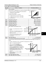
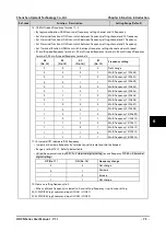
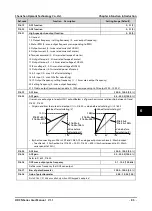
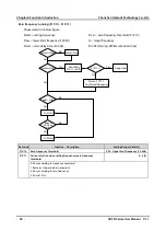
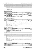
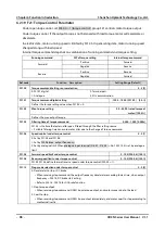
F15.39
Action selection when analogue input exceeding limit
00000 - 21133 [0000]
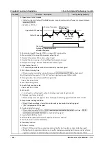
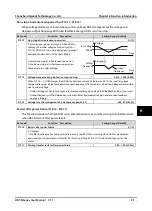
If corresponding analogue > F15.40 or analogue < F15.41 and go through F15.42, detect analogue input is
exceeding limit.
After detection, HD3N runs according to setting of thousands when F15.41 ≤ analogue ≤ F15.40.
Unit: Action of HD3N when input exceeding limit
•
0: Coast to stop.
•
1: Emergency stop.
•
2: Decelerate to stop.
•
3: No action.
Ten: Select analogue input terminal
•
0: No analogue terminal.
•
1: Potentionmeter on keypad.
•
Valid only when LED keypad adopted.
•
2: AI1.
•
3: AI2.
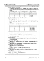
Hundred: Condition for detecting analogue
exceeding limit
•
0: Detect all the time.
•
1: Detect according to command.
Thousand: Running selection after exceeding
•
0: Do not permit auto running.
•
1: Permit auto running.
Ten thousand: Action at analogue exceeding limit
•
0: Do not report external fault (E0024).
•
1: Report external fault (E0024), can not auto
reset.
•
2: Report external fault (E0024), can auto reset.
•
when conditions are invalid, external fault
(E0024) can auto reset.
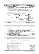
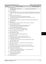
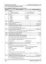
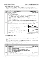
F15.40
Upper limit of exceeded analogue input
F15.41 - 100.0 [100.0%]
F15.41
Lower limit of exceeded analogue input
0.0 - F15.40 [0.0%]
F15.42
Detection time for exceeded analogue
0.00 - 50.00 [5.00s]
F15.43
Terminal output delay
0.0 - 100.0 [0.0s]
F15.44
Detection time for exceeded analogue at start
0.00 - 50.00 [15.00s]
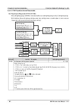
6.2.14
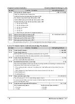
F16: Analogue I/O Terminal Parameters
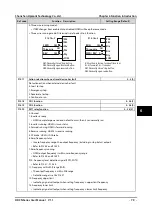
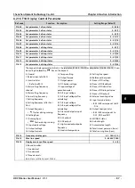
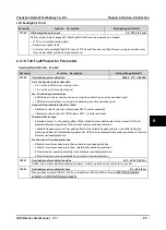
Ref. code
Function Description
Setting Range [Default]
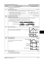
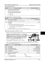
F16.00
Keypad with potentiometer function
0 - 15 [0]
F16.01
AI1 function
0 - 15 [2]
F16.02
AI2 function
0 - 15 [5]
Note: F16.00 is valid only when LED keypad is adopted.
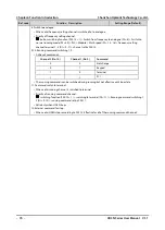
0: Used.
1: Upper frequency setting.
•
F00.07 = 1 (analogue input sets upper limit frequency setting channel), upper limit frequency is set by
corresponding input voltage.
2: Frequency setting.
•
F00.10 = 3 (analogue input sets frequency setting channel), setting frequency is set by corresponding
input voltage.
3: Aux frequency setting.
•
F19.00 = 4 (analogue sets aux frequency setting), aux frequency is set by corresponding input voltage.
4: Process PID setting.
•
F04.01 = 1 (analogue sets process PID setting), process PID setting is set by corresponding input
voltage.
5: Process PID feedback.
•
F04.02 = 0 ( analogue inputs process PID feedback), process PID feedback is set by corresponding input
voltage.
6

