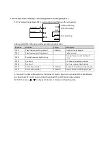
5. To use terminal to start/stop, and use communication to set running frequency
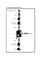
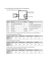
1. DI1 is forward signal input, DI2 is reverse signal input. Below is the connection.
2. Power on, and set function parameters according to connection.
Ref. code
Function
Setting
Meaning
F00.10
To select frequency setting channel
2
SCI communication setting
F00.11
To select command setting channel
1
Running command set by terminal
F03.01
Acc. time 1
-
Acc. time, adjust according to actual
F03.02
Dec. time 1
-
Dec. time, adjust according to actual
F15.00
DI1 function selection
2 (default)
Forward (terminal forward signal input)
F15.01
DI2 function selection
3 (default)
Reverse (terminal reverse signal input)
F15.18
DO1 function selection
2 (default)
Inverter is running
F17.00
Data format
0 (default)
1-8-2 format, no parity, RTU
F17.01
Baut rate
3 (default)
9600bps
F17.02
Local address
2 (default)
3. Connect K1, motor forward run; disconnect K1, motor stops running. Connect K2, motor reverse run;
disconnect K2, motor stops running. Connect or disconnect both K1 and K2, motor stops running.
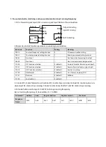
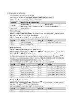
4. SCI code 0x06 reads to register 0x3201 to change running frequency.
E.g: set running frequency of slave address 2 = 15.00Hz:
Command /
Response
Frame
Address
Code
Register address
Register content
Checksum
0x02
0x06
0x32
0x01
0x11
0x94
0xDB
0x7E
DI1
COM
DI2
Fault indicating
Output indicating
signal at running
Forward
Reverse
K1
K2
DO1
R1C
R1B
R1A
A
B
PLC
485+
485-

