background image

Shenzhen Hpmont Technology Co., Ltd. 

Chapter 4 Electrical Installation 

HD3N Series User Manual    V1.1 

-  27  - 

4.4.6


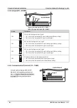
Communication Terminal (90 - 400kW) 

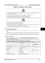
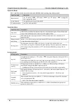
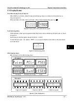
Do not use communication terminal and RJ45 
simultaneously. 


Terminal 

Description 

485+ 

485- 


Pin 

Difinition 

1,3 

+5V 

485+ 

4,5,6 

GND 

485- 

Unused 


4.4.7


Control Terminal Wiring 

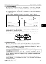
To reduce the interference and attenuation of control signal, length of control cable should limit within 
50m. There should be more than 0.3m between the control cable and the motor cable. 

The control cable must be shielded cable. The analogue signal cable must be shielded twisted pair. 


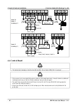
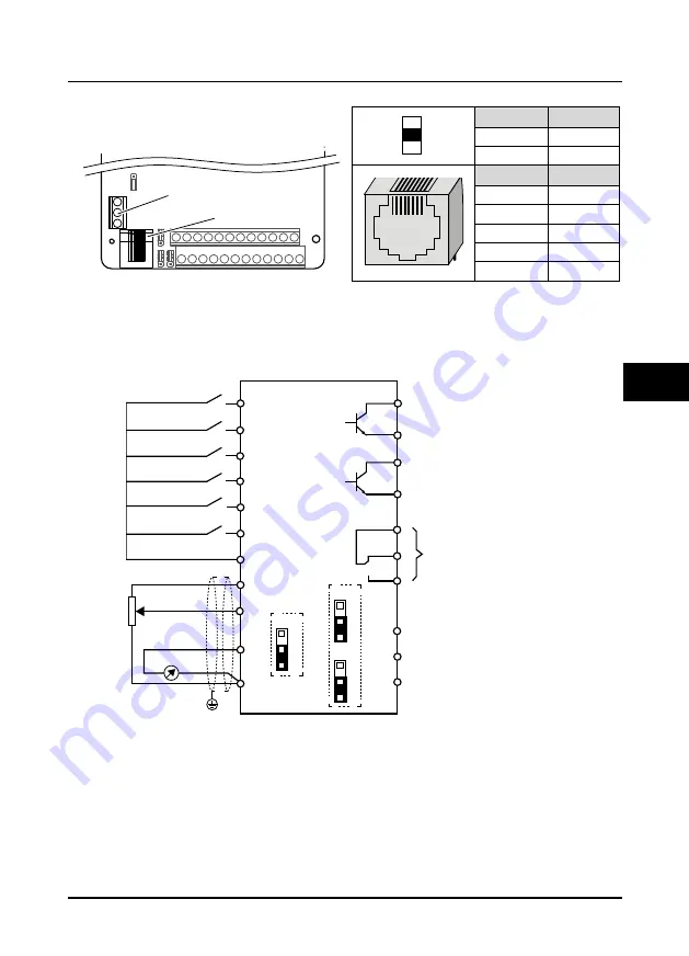
Figure 4-5 HD3N control board connection 

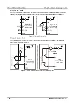
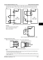
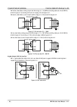
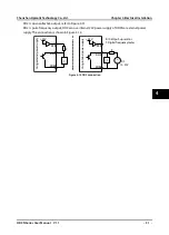
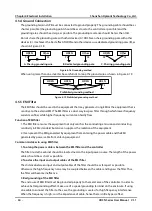
Digital input (DI) connection 

Compatible with DC/AC input signal. 


Input voltage: 15VDC - 56VDC, compatible with 24VDC/36VDC/48VDC. 


Input voltage: 12VAC - 54VAC, compatible with 36VAC/48VAC.


RJ45

Control Board

Terminal

A

B

RJ45

1

8

DI1

DO2

DO1

CME

R1A

R1C

R1B

Programmable

relay output

Programmable open
collector channel 1

Programmable open
collector channel 2

GND

AO1

AO2

Analogue output channel 1

Input terminal 1

Input terminal 2

Input terminal 3

Input terminal 4

Input terminal 5

Input terminal 6

DI2

DI3

DI4

DI5

DI6

COM

AI1

AI2

+10

AI1

AI2

HD3N

GND

Analogue output channel 2

COM

PE

Control Board

AI2

C

N

2

3

1

AO1

C

N7

3

1

AO2

C

N

8

3

1

Summary of Contents for HD3N Series

Page 1: ...HD3N Series High performance Smart Inverter V1 1 2018 09 HD3N Series High performance Smart Inverter User Manual ...

Page 2: ...ease do not use this product until you have fully understood safety precautions Note Preserve this Manual for future use If you need the User Manual due to damage loss or other reasons please contact the regional distributor of our company or directly contact our company Technical Service Center If you still have some problems during use please contact our company Technical Service Center Due to p...

Page 3: ...Three phase AC power supply MCCB Contactor AC input reactor accessory EMI filter HD3N EMI filter Motor Braking resistor accessory Connectionwithperipheral devices AC output reactor accessory ...

Page 4: ... section 3 3 for installation direction and space See section 3 4 for structural specifications Input and output wiring power terminal wiring see section 4 2 For power terminal description see section 4 3 See section 4 4 for control board instructions For the selection of brake unit and braking resistor see section 8 2 See section 8 3 for reactor selection ...

Page 5: ......

Page 6: ...t running frequency via keypad 1 Power on HD3N Use keypad to set motor parameter F08 00 F08 04 running frequency F00 13 and Acc Dec time F03 01 F03 02 Ref code Function Setting Description F00 10 Frequency setting channel selection 0 default Running frequency set by keypad digital setting F00 11 Command setting channel selection 0 default Keypad runs command channel F00 13 Running frequency digita...

Page 7: ...equency set according to actual F03 01 Acc time 1 Acc time set according to actual F03 02 Dec time 1 Dec time set according to actual F15 00 DI1 function selection 2 default Forward terminal forward signal input F15 01 DI2 function selection 3 default Reverse terminal reverse signal input 3 Connect K1 motor will forward run Disconnect it motor stops running Connect K2 motor Reverse run Disconnect ...

Page 8: ...time adjust according to actual F15 00 DI1 function selection 2 default Forward terminal forward signal input F15 01 DI2 function selecrtion 3 default Reverse terminal reverse signal input F16 01 Analogue input AI1 function selection 2 default Frequency setting channel set by AI1 3 Adjust AI1 to set running frequency 4 Connect K1 motor forward run disconnect K1 motor stops running Connect K2 motor...

Page 9: ... DI2 function selection 3 default Reverse terminal reverse signal input F15 18 DO1 function selection 2 default Inverter is running F17 00 Data format 0 default 1 8 2 format no parity RTU F17 01 Baut rate 3 default 9600bps F17 02 Local address 2 default 3 Connect K1 motor forward run disconnect K1 motor stops running Connect K2 motor reverse run disconnect K2 motor stops running Connect or disconn...

Page 10: ...ss 2 default 3 Register 0x3200 of SCI communication code 0x06 starts stops inverter whose local address 2 E g Forward start command is as following Command Response Frame Address Code Register address Register content Checksum 0x02 0x06 0x32 0x00 0x10 0x01 0x4B 0x41 E g Dec stop command is as following Command Response Frame Address Code Register address Register content Checksum 0x02 0x06 0x32 0x...

Page 11: ...at stop Press button to start auto tuning Oscillation and over current may occur during motor rotary In this case press button immediately to stop tuning and adjust Acc Dec time F09 15 LF oscillation suppression of motor and F09 16 HF oscillation suppression of motor to reduce the oscillation When auto tuning finished F08 04 and F08 07 F08 16 are refreshed automatically Ref code Function Ref code ...

Page 12: ...tting By setting analogue bias and gain F00 10 Frequency setting channel 3 Analogue setting F00 18 Prevent reverse 1 Forbid reverse F16 01 AI1 function 0 No function F16 02 AI2 function 2 Frequency setting F16 08 AI2 bias 20 0 AI2 analogue bias F16 09 AI2 gain 1 20 AI2 analogue gain Analogue 4 20mA output AO1 AO2 can select current output default 0 20mA Short connect pin2 3 on CN7 for AO1 and shor...

Page 13: ......

Page 14: ...er 4 Electrical Installation 17 4 1 Precautions 17 4 2 Peripheral Accessories Selection 17 4 2 1 Wiring Specifications of Input and Output 17 4 2 2 Power Terminal Lug 19 4 3 Main Circuit Terminals and Wiring 19 4 3 1 Supply and Motor Terminal 19 4 3 2 Supply and Motor Connection 21 4 4 Control Board 22 4 4 1 Control Terminal 7 5 75kW 23 4 4 2 Control Terminal 90 400kW 24 4 4 3 Jumper 7 5 75kW 25 4...

Page 15: ...meter 57 6 2 5 F04 Process PID Control 58 6 2 6 F05 External Setting Curve Parameter 61 6 2 7 F06 Multi speed and Simple PLC 63 6 2 8 F07 Wobble Function Parameter 66 6 2 9 F08 Asyn Motor Parameters 67 6 2 10 F09 V f Control Parameters 69 6 2 11 F10 Motor Vector Control Speed loop Parameters 71 6 2 12 F11 Motor Vector Control Current loop Parameters 72 6 2 13 F15 Digital I O Terminal Parameters 73...

Page 16: ...01 7 1 Troubleshooting 101 7 2 Maintenance 104 Chapter 8 Accessories 107 8 1 Extension Keypad and Accessories 107 8 2 Braking Unit and Braking Resistor 109 8 3 Reactor Selection 110 Appendix A Parameters 111 Appendix B Communication Protocol 143 ...

Page 17: ......

Page 18: ...nd Precautions 2 Product Information 3 Machenical Installation 4 Electrical Installation 5 Operation Instructions B Communication Protocol A Parameters 6 Function Introduction 7 Troubleshooting and Maintenance 8 Accessories ...

Page 19: ......

Page 20: ... the output torque ratings will become worse due to the motor cooling is less effective In that case we suggest that you should choose variable frequency motor Thermal protection of motor When choose adaptive motor HD3N can effectively implement the motor thermal protection Otherwise it must adjust the motor protection parameters or other protection measures to ensure that the motor is at a safe a...

Page 21: ...leakage current so users need to confirm the reliable grounding before connect to the power supply The grounding should comply with the local relative IEC standard 1 3 About HD3N No capacitor or varistor on the output side Since HD3N output is PWM wave it is strictly forbidden to connect capacitor for improving the power factor or varistor for lightning protection to the output terminals so as to ...

Page 22: ...t be derating and should be 60 within rated value of controller Lightning surge protection HD3N internal design has lightning surge over current protection circuit and has certain self protection capacity against the lightning Altitude and derating In area where altitude exceeds 1000 meters HD3N should be derating since the heatsink efficiency will be reduced because of the tenuous air The rated v...

Page 23: ......

Page 24: ... Nameplate HD3N 4T7P5 G Product Series Power Supply Voltage 380 460VAC 4 Three phase input T Input Phase Power General G Product Type Product model Motor power Input specification Output specification Software version Serial number MODEL HD3N 4T7P5G 7 5kW POWER 3PH 380 460V 19A 50 60Hz INPUT 11kVA 0 460V 17A 0 400Hz OUTPUT 1 00 Version 2 ...

Page 25: ...39 62 60 Frame 5 HD3N 4T037G 37 49 77 75 Frame 6 HD3N 4T045G 45 59 92 90 Frame 6 HD3N 4T055G 55 72 113 110 Frame 7 HD3N 4T075G 75 100 156 152 Frame 7 HD3N 4T090G 90 116 180 176 Frame 8 HD3N 4T110G 110 138 214 210 Frame 8 HD3N 4T132G 132 167 256 253 Frame 9 HD3N 4T160G 160 200 307 304 Frame 9 HD3N 4T200G HD3N 4T200G C 200 250 385 380 Frame 10 HD3N 4T220G HD3N 4T220G C 220 280 430 426 Frame 10 HD3N ...

Page 26: ...pad is adopted Programmable input output terminal Programmable input output terminal Process PID adjustment function In built process PID module Simple PLC function In built simple PLC module for timing and multi frequency output Wobble function In built wobble function module Length control function In built length control module Protection Functions Stall overvoltage Busbar voltage can auto cont...

Page 27: ...tting check status parameter and fault code etc Parameter copy LED can achieve parameter copying Environment Running temperature 10 40 max 50 air temperature fluctuation is less than 0 5 min The derating value of the output current of HD3N shall be 2 for each degree centigrade above 40 Max allowed temperature is 50 Storage temperature 40 70 Location for use Indoor preventing from direct sunlight n...

Page 28: ...td Chapter 2 Product Information HD3N Series User Manual V1 1 9 2 5 Parts of Inverter Connection holes of control terminal Connection holes of power terminal Keypad Fan Upper cover Lower cover Nameplate Certification Mounting hole 2 ...

Page 29: ......

Page 30: ...he installation site meets the following requirements Do not install at the direct sunlight moisture water droplet location Do not install at flammable explosive corrosive gas and liquid location Do not install at oily dust fiber and metal powder location Be vertical installed on fire retardant material with a strong support Make sure adequate cooling space for HD3N so as to keep ambient temperatu...

Page 31: ...shown in Table 3 1 Table 3 1 Installation space Inverter power 55kW 75kW A Left Right 50mm 150mm B UP Down 100mm 350mm C Upper air vent 50mm 100mm D Lower air vent 50mm 100mm 123 When one inverter is mounted on top of another an air flow diverting plate should be fixed between them Just as shown in Table 3 2 Table 3 2 Installation of several inverters Inverter power 55kW 75kW A 50mm 100mm B 50mm 1...

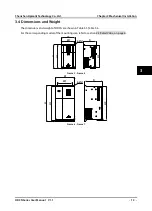
Page 32: ...s User Manual V1 1 13 3 4 Dimensions and Weight The dimensions and weight of HD3N are shown in Table 3 3 Table 3 4 For the corresponding model of the mounting size refer to section 2 3 Rated Value on page 6 Frame 3 Frame 5 Frame 6 Frame 7 H2 H H1 W1 W D 4 Ød H H1 H2 W1 W 4 Ød D 3 ...

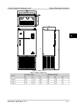
Page 33: ... d Frame 3 140 260 155 122 248 235 6 5 4 Frame 4 180 298 175 160 284 270 6 8 3 Frame 5 220 375 190 200 360 345 7 13 Frame 6 260 440 230 220 420 403 8 21 Frame 7 300 555 270 240 535 515 10 36 Frame 8 338 580 315 270 560 538 10 41 5 Frame 9 400 840 340 320 816 792 10 73 Frame 10 520 780 350 380 752 720 12 95 Frame 11 620 880 360 480 848 823 14 120 Frame 12 780 1350 394 620 1320 1281 14 260 H H1 H2 W...

Page 34: ...stallation HD3N Series User Manual V1 1 15 Frame 10 Frame 12 C Table 3 4 HD3N C dimensions Size C Dimension mm Mounting size mm W H D W1 D1 d Frame 10 520 1120 350 450 250 16 Frame 11 620 1223 360 550 260 16 Frame 12 780 1681 394 620 290 18 W1 W D H D1 4 Ød 3 ...

Page 35: ......

Page 36: ...nor short circuiting Do not do dielectric strength test on HD3N For HD3N with more than 2 year s storage please use regulator to power it slowly Do wiring connection of the braking resistor or the braking unit according to the wiring figure Make sure the terminals are fixed tightly Do not connect the AC supply cable to the output terminals U V W of HD3N Do not connect the phase shifting capacitors...

Page 37: ...200 125 50 50 25 Frame 7 HD3N 4T075G 250 160 50 50 25 Frame 7 HD3N 4T090G 250 160 95 70 50 Frame 8 HD3N 4T110G 350 350 120 120 60 Frame 8 HD3N 4T132G 400 400 120 120 60 Frame 9 HD3N 4T160G 500 400 185 185 95 Frame 9 HD3N 4T200G HD3N 4T200G C 600 600 240 240 120 Frame 10 HD3N 4T220G HD3N 4T220G C 600 600 120 2 1 120 2 1 120 Frame 10 HD3N 4T250G HD3N 4T250G C 800 600 120 2 1 120 2 1 120 Frame 11 HD3...

Page 38: ... N M Max outer diameter d mm Frame 3 M4 1 2 1 5 10 2 Frame 4 M5 2 3 2 5 12 3 Frame 5 6 M6 4 0 5 0 17 0 Frame 7 M8 9 0 10 0 20 Frame 8 M10 17 6 22 5 30 Frame 9 M12 31 4 39 2 37 Frame 10 M12 31 4 39 2 40 Frame 11 M12 31 4 39 2 40 Frame 12 M16 48 6 59 4 40 4 3 Main Circuit Terminals and Wiring The bare portions of the power cables must be bound with insulation tapes Ensure that AC supply voltage is t...

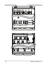
Page 39: ...zhen Hpmont Technology Co Ltd 20 HD3N Series User Manual V1 1 Frame 8 Frame 11 Frame 10 Frame 11 C supply and motor terminal Frame 12 Frame 12 C supply and motor terminal PE L1 L2 L3 P1 POWER PE U V W MOTOR PE L1 L2 L3 POWER PE U V W MOTOR ...

Page 40: ...two of the output terminals U V W or modify F00 17 to change the motor direction The supply and motor connection are shown as Table 4 5 Refer to section 4 2 Peripheral Accessories Selection on page 17 for product options Refer to section 8 2 Braking Unit and Braking Resistor on page 109 for braking resistors and braking units Refer to section 8 3 Reactor Selection on page 110 for reactor Table 4 5...

Page 41: ...n of external devices not be changed If connect the communication terminal of the control circuit to the PC choose RS485 232 isolating converter which meets the safety requirement Only connect the relay terminal to AC 220V voltage signal Other control terminal are strictly forbiden for this connection L1 L2 L3 PE Braking resistor Supply ground P1 DC reactor U V W PE Braking unit BR1 BR2 Supply gro...

Page 42: ...voltage 15VDC 56VDC compatible with 24VDC 36VDC 48VDC Input voltage 12VAC 54VAC compatible with 36VAC 48VAC Input impedance 6 2kΩ DI6 can be selectable for high frequency input max frequency 10kHz P24 COM Digital power supply Digital input use 24V power supply max output current is 200mA COM is isolated to CME SEL Digital input common terminal SEL and P24 are connected by default Disconnect SEL an...

Page 43: ...Anglogue ground DI1 DI6 Digital input Programmable bipolar optional input signal Input voltage 0 30VDC DI1 DI5 input impedance 4 7kW DI6 input impedance 1 6kΩ DI6 can be selectable for high frequency input max frequency 50kHz P24 COM Digital power supply Digital input use 24V as supply max output current is 200mA COM is isolated to CME SEL Digital input common terminal SEL and P24 are connected by...

Page 44: ...E and GND can increase immunity Pin 1 2 are short connected PE and GND are not connected factory setting Pin 2 3 are short connected PE and GND are connected CN6 Impedance selection when AI2 current input Pin 1 2 are short connected impedace 500Ω factory setting Pin 2 3 are short connected impedace 250Ω CN7 AO1 can select output voltage or current signal Pin 1 2 are short connected AO1 outputs vol...

Page 45: ... voltage signal factory setting Pin 2 3 are short connected AO1 inputs current signal CN8 AO2 can select voltage or current signal Pin 1 2 are short connected AO2 inputs voltage signal factory setting Pin 2 3 are short connected AO2 inputs current signal CN9 SCI communication can select proper resistance Pin 1 2 are short connected select the proper resistance Pin 2 3 are short connected no resist...

Page 46: ...ded cable The analogue signal cable must be shielded twisted pair Figure 4 5 HD3N control board connection Digital input DI connection Compatible with DC AC input signal Input voltage 15VDC 56VDC compatible with 24VDC 36VDC 48VDC Input voltage 12VAC 54VAC compatible with 36VAC 48VAC RJ45 Control Board Terminal A B RJ45 1 8 DI1 DO2 DO1 CME R1A R1C R1B Programmable relay output Programmable open col...

Page 47: ...C signal Source Drain Using external power supply the source drain connection are shown in Figure 4 7 Remove the connector between SEL and P24 Figure 4 7 Source Drain connection when using external power 24V COM P24 SEL K DI1 DI6 24V COM P24 SEL K DI1 DI6 12 30V DC Dry contact Using internal power supply Dry contact Using external power supply Current Current 24V P24 SEL DI1 COM DI6 6 1 COM Extern...

Page 48: ...ection The AI1 is voltage input and the range is 0 10V as shown in Figure 4 10 Figure 4 10 AI1 connection Note 1 To reduce the interference and attenuation of control signal length of control cable should limit within 50m and the shield should be reliably grounded 2 In serious interference occasions the analogue input signal should add filter capacitor and ferrite core as shown in Figure 4 10 Exte...

Page 49: ... selecting internal 10V of HD3N refer to Figure 4 10 selecting 10V external supply refer to Figure 4 12 AI2 are selected as current input and the range is 0 20mA refer to Figure 4 12 Figure 4 12 AI2 connection 90 400kW Digital Output DO Connection DO1 is open collective output DO1 can use internal 24V power supply of HD3N or external power supply The connection is shown in Figure 4 13 Figure 4 13 ...

Page 50: ...to Figure 4 13 DO2 is pulse frequency output DO2 can use internal 24V power supply of HD3N or external power supply The connection is shown in Figure 4 14 Figure 4 14 DO2 connection DO2 COM 24V R P24 DO2 COM 24V R P24 f f 12 30V DC Using internal power supply Using external power supply R 10kΩpull up resistor f Digital frequency meter 4 ...

Page 51: ... the noise source can be controller braking unit and contactor Noise receiver can be automation equipment encoder and sensor etc The mechanical system is divided into different EMC areas according to electrical characteristics The recommended installation positions are shown in Figure 4 15 Figure 4 15 System wiring Explanation All areas should be isolated in space to achieve electromagnetic decoup...

Page 52: ...hown in Figure 4 17 Figure 4 17 Shielded cable connection 4 5 3 Motor Connection The longer cable between the controller and the motor is the higher frequency leakage current will be causing the inverter output current to increase as well This may affect peripheral devices When the cable length is longer than 100 meters it is recommended to install AC output reactor and adjust the carrier frequenc...

Page 53: ... and conducting sensitivity in EMC standard but also can suppress the radiation of the equipment 2 It can prevent the EMI generated by equipment from entering the power cable and the EMI generated by power cable from entering equipment Common mistakes in using EMI filter 1 Too long the power cable is between the EMI filter and the controller The filter inside the cabinet should be located near to ...

Page 54: ...ly decreased when the distance between the output cables and the signal cables is above 0 3m Reducing RF interference The I O cables and the controller produce radio frequency interference A noise filter can be installed both on the input side and output side and shield them with iron utensil to reduce RF interference The wiring distance between the controller and the motor should be as short as p...

Page 55: ......

Page 56: ...high temperature 5 1 Function Description Note In the following sections you may encounter control running and status of HD3N description many times Please read this section It will help you to correctly understand and use the functions to be discussed Frequency setting channel The final setting frequency of HD3N is set by main frequency setting channel F00 10 and aux frequency setting channel F19...

Page 57: ...or on keypad is lighting Stop status parameter will flash on LCD During running the parameters with X can not be modified during running refer to appendix A Running modes Running modes Description Jog start In keypad control mode press button to jog start frequency running set F00 15 F03 15 and F03 16 In terminal control mode when receiving DI jog start command No 20 25 function HD3N runs accordin...

Page 58: ...ers can select LED keypad Refer to Figure 5 1 The standard LCD keypad cannot be dismantled Wiring of LED is shown in section 4 4 5 and 4 4 6 Figure 5 1 Keypad LCD keypad Standard 2 3 4 5 8 9 10 1a 1b 1c 11 2 3 4 5 8 8 9 9 10 11 7 7 1a 1b 1c LED keypad Optional HD LED P S HD LED P ENT SHF JOG PRG STOP RUN Hz A V RPM REV FWD ALM LO RE LOCK 1a 1b 1c 2 3 4 5 10 11 6 5 ...

Page 59: ... frequency A current V voltage RPM rotoray speed b Display area Display parameter in normal state display fault code when fault occurs The value is modifiable when it is flashing Display Meaning Display Meaning Display Meaning Display Meaning 0 A J U 1 b L u 2 C n y 3 c o 4 d P Dot 5 E q Full display 6 F r No display 7 H S Flashing Modifiable 8 h T 9 i t 123 2 Program Exit Enter or exit 3 Jog Jog ...

Page 60: ...the fault press button or use external fault reset terminal or communication reset command Figure 5 3 Fault alarming status Other display status Refer to Figure 5 4 for other display status Figure 5 4 Other display status FWD Hz A V RPM LO RE LOCK REV ALM FWD Hz A V RPM LO RE LOCK REV ALM FWD Hz A V RPM LO RE LOCK REV ALM PW set su ccessfully PW has been clea red Unlock su ccess Reset Parameter au...

Page 61: ...s key one time Modify the internal No of function group Increase by 1 according to the present modified bit Modify function value Increase by 1 according to the present modified bit Select function group Cycle according to y R F d Modify No function Decrease by 1 when press this key one time Modify the internal No of function group Decrease by 1 according to the present modified bit Modify functio...

Page 62: ...ing to Figure 5 8 If password have been set unlock according to Figure 5 7 then set F00 00 according to Figure 5 8 Figure 5 8 Modify user password Clear user password If password have been set unlock according to Figure 5 7 then clear F00 00 according to Figure 5 9 Figure 5 9 Clear user password FWD Hz A V RPM LO RE LOCK REV ALM FWD Hz A V RPM LO RE LOCK REV ALM FWD Hz A V RPM LO RE LOCK REV ALM F...

Page 63: ...ter keypad displays dnLd when copying finished keypad will display F01 03 Figure 5 11 Copy to control board Note 1 When copying to control board it displays dFAiL which means that EEPROM storage parameters of keypad do not mathc with function parameters of HD3N First copy the setting value of the correct function code to EEPROM of keypad and then copy to control board 2 When copying parameter keyp...

Page 64: ...lti speed and Simple PLC on pages 63 66 F07 Wobble Function Parameter on pages 66 67 F08 Asyn Motor Parameters on pages 67 69 F09 V f Control Parameters on pages 69 71 F10 Motor Vector Control Speed loop Parameters on pages 71 72 F11 Motor Vector Control Current loop Parameters on pages 72 73 F15 Digital I O Terminal Parameters on pages 73 83 F16 Analogue I O Terminal Parameters on pages 83 86 F17...

Page 65: ...are current restriction 0 Do not restrict 1 Restrict Bit13 Software current restriction 0 Do not restrict 1 Restrict Bit12 Stall overvoltage 0 Invalid 1 Valid Hundr eds Bit11 Control mode 0 Speed control 1 Torque control Bit10 Speed limitation 0 Below limitation 1 Above limitation Bit9 Unused Bit8 Auto tuning 0 Not in auto tuning 1 In suto tuning Tens Bit7 DC brake 0 Invalid 1 Valid Bit6 Unused Bi...

Page 66: ...of 10V d00 29 AI2 input Actual value Display AI2 input voltage current calculated by filter When AI2 selects voltage input 0V corresponds to 0 0 and 10V corresponds to 100 0 When AI2 selects current input 0mA corresponds to 0 0 20mA corresponds to 100 0 d00 30 AI2 input after calculating Actual value Display AI2 input voltage current which is calculated by gain and bias Refer to d00 29 d00 35 DI6 ...

Page 67: ...status Actual value Display output terminal status Each bit binary of this parameter stands for different physical sources which are in the below table 0 Output terminals disconnect with common terminals 1 Output terminals connect with common terminals Bit7 Bit6 Bit5 Bit4 Bit3 Bit2 Bit1 Bit0 RLY1 DO2 DO1 123 d00 52 MODBUS communication status Actual value Display MODBUS communication status 0 Norm...

Page 68: ...cy of HD3N 50 00 400 00 50 00Hz Defines the max frequency that HD3N is allowed to output V f max 400Hz Vector control max 200Hz Please set F00 06 according to nameplate of motor and actual running conditions F00 07 Upper limit of running frequency setting channel 0 7 0 Defines the max frequency that system is allowed to run and use F00 07 to select setting channels to set the upper limit frequency...

Page 69: ...Start and stop by using corresponding external terminals DI treminal is set as FWD DI 2 REV DI 3 JOGF1 DI 20 JOGR1 DI 21 JOGF2 DI 22 and JOGR2 DI 23 refer to group F15 2 SCI Start and stop by SCI port according to communication protocol F00 12 M key function 0 2 2 Note Valid when LED keypad adopted only 0 Switch running direction Switch running direction by button F00 11 0 it is valid Do not save ...

Page 70: ...ommand HD3N will not respond to jog command within F00 16 After the interval of jog is completed it immediately executes the arrived jog command As show in figure F00 17 Running direction 0 1 0 0 The same as running command 1 Opposite to running command F00 18 Reverse 0 1 0 This function is valid when F00 11 0 1 2 0 Permitted 1 Prohibitted HD3N responds to FWD REV commands only If frequency 0Hz HD...

Page 71: ... selection of zero speed under V f control 0 Do not process 1 HD3N does not output 2 HD3N runs at DC brake Ten Action selection of zero speed under open loop vector control Hundred Action selection of zero speed under torque control 0 Do not process 1 HD3N does nto output 2 HD3N runs at DC brake 3 HD3N runs at pre excitation F00 27 Command source binding frequency source 000 ddd 000 Valid only for...

Page 72: ...er initialization download 0 6 0 0 No operation HD3N is in regular parameter read write status Whether can change the parameter depends on user password status and the actual running condition of HD3N 1 Restore to factory settings Except F01 00 F01 02 F01 03 Group F08 F19 15 F19 19 F19 24 F20 08 F20 09 F20 21 F20 37 F23 00 and Group y Steps If set F01 02 1 press to ensure and the parameters are re...

Page 73: ... Rotate speed tracking re start When the result is lower than F02 02 HD3N starts from starting DWELL frequency Tracks the rotate speed and direction of motor automatically smooth and low impact is applied to motor which is rotating Rotate speed tracking is valid only during the process of switching from stop to running It is invalid during running when the direction switches F02 01 Start delay tim...

Page 74: ...to rated current of HD3N It sets current value of starting DC brake and stop DC brake If setting DC brake current is 5 times higher than rated current of motor the inputing current will be 5 times rated current of motor DC brake current is valid for both start and stop DC brake F02 05 0 there is no DC brake acting F02 05 is valid only when F02 00 1 F02 06 Compensation for full speed tracking 0 000...

Page 75: ...added during stop process HD3N does not output during waiting time of stop brake F02 17 can avoid overshoot at point B start time of brake of high power motor F02 04 sets the current at DC brake F02 18 0 there is no DC brake acting F02 16 F02 18 is valid only when F02 13 2 F02 19 Jog control mode 00 11 10 Units 0 Can not jog the start and stop function When jog run start mode F02 00 and stop mode ...

Page 76: ... time Select Acc Dec time by No 26 27 of DI terminal or F03 09 F03 10 when HD3N is running Switching of Acc Dec mode The Acc Dec modes linear or S curve can be set by F03 00 or No 28 function of DI terminal Note If braking units are not adopted correctly dec speed is too high or load interia is too large over pressure will occur to HD3N Please select suitable braking unit increase the dec time or ...

Page 77: ...04 01 Setting channel selection 0 7 0 0 Digital Set by F04 03 1 Analogue Set by analogue input voltage Max analogue input corresponds to 100 of PID setting refer to group F16 2 Terminal pulse Set the terminal pulse input Max input pulse frequency corresponds to 100 of PID setting refer to group F16 3 AI1 4 AI2 7 Potentionmeter Valid when LED keypad adopted only F04 02 Feedback channel selection 0 ...

Page 78: ...erminal pulse 3 AI1 4 AI2 7 Potentionmeter Valid when LED keypad adopted only F04 12 Lower limit channel of PID regulator 0 7 0 When PID serves as aux frequency setting channel F04 12 is invalid the lower limit REV frequency upper limit F04 12 is valid only when PID F04 00 1 and prohibit reverse F04 18 0 0 Set by F04 14 1 Analogue setting Set by analogue input voltage refer to F16 2 Terminal pulse...

Page 79: ...ing is within switching point 1 and 2 3 Frequency Select group 1 when PID output frequency switching point 1 F04 24 Select group 2 when PID output frequency switching point 2 F04 25 Select linear interpolation when PID output frequency is within switching point 1 and 2 F04 24 PID parameter switching point 1 0 0 F04 25 0 0 F04 25 PID parameter switching point 2 F04 24 100 0 100 0 F04 27 Rpm 1 9999 ...

Page 80: ...lyline F05 11 100 0 100 0 F05 10 Max setting corresponding value of polyline 0 0 100 0 100 0 F05 11 Inflection point 2 setting of polyline F05 13 F05 09 100 0 F05 12 Inflection point 2 corresponding value 0 0 100 0 100 0 F05 13 Inflection point 1 setting of polyline F05 15 F05 11 0 0 F05 14 Inflection point 1 corresponding value 0 0 100 0 0 0 F05 15 Min setting of polyline 0 0 F05 13 0 0 F05 16 Mi...

Page 81: ...en setting the frequnecy skip output frequency of HD3N changes smoothly according to Acc Dec curve setting Skip frequency setting is invalid when PID control or aux frequency setting selects process PID F05 21 Digital setting 2 of jog run frequency 0 00 Upper limit frequency 5 00Hz When terminal selects jog run 2 HD3N runs according to F05 21 F05 22 Curve selection for potentionmeter 0 3 3 Note Va...

Page 82: ... F00 09 F00 08 5 00Hz F06 14 Multi frequency command 15 F00 09 F00 08 5 00Hz Define the intial value of each speed under multi speed mode and PLC mode During multi speed running tens of F06 17 F06 45 PLC phase setting sets direction of each speed and hundreds sets time of each speed F06 15 Simple PLC control selection 0 1 0 0 PLC is invalid 1 PLC is enabled Set F06 16 F06 46 according to actual co...

Page 83: ...e at the right Note Compared with mode 1 mode 2 memorize the running frequency at stop and restarts from this frequency Hundred PLC state saving selection at power failure 0 Do not save Do not save PLC running state HD3N starts from the first phase after power on 1 Save Save PLC running state including phase running frequency and the running time HD3N runs according to tens of F06 16 Thousand PLC ...

Page 84: ...rnal command Runing direction command If direction can not change HD3N runs according to the previous phase Hundred PLC phase Acc Dec time selection 0 Acc Dec time 1 1 Acc Dec time 2 2 Acc Dec time 3 3 Acc Dec time 4 4 Set by Acc Dec speed F06 18 Phase 1 running time 0 0 3276 7 5 0 F06 20 Phase 2 running time 0 0 3276 7 0 0 F06 22 Phase 3 running time 0 0 3276 7 0 0 F06 24 Phase 4 running time 0 0...

Page 85: ...d it runs the waiting time F07 03 at wobble pre set frequency F07 02 and then enter wobble running 1 Manually terminal entry way Set DI No 36 function wobble entry function and when this signal is valid HD3N enters wobble statue When invalid HD3N exits wobble state and the running frequency remains F07 02 Ten Wobble control refer to 07 04 0 Relate to wobble centric frequency 1 Relate to max Output...

Page 86: ...cy F07 06 Wobble period 0 1 999 9 10 0s Defines the time during which wobble goes up and down F07 07 Triangular wave rising time 0 0 100 0 50 0 Defines the running times that wobble rise and fall It relates to F07 06 Unit s Running time at rising F07 06 F07 07 Running time at falling F07 06 1 F07 07 6 2 9 F08 Asyn Motor Parameters Formula of mutual inductance Mutual inductance F08 10 F08 01 2 3π F...

Page 87: ...e measurement When motor is in stationary state stator resistance will be auto measured and written into F08 07 Steps 1 Correctly set motor parameter F08 00 F08 04 2 When F08 06 2 set proper acc time F03 01 and dec time F03 02 free motor axis from load and make sure it is safe 3 When F08 06 1 or 2 or 3 press then press button to exit to parameter display state and press button to start auto tuning...

Page 88: ... V2 F2 and V3 F3 to apply to special load According to actual condition set proper curve to meet requirements of load characteristics F09 07 Torque boost of motor 0 0 30 0 2 0 F09 08 Cut off point used for manual torque boost of motor 0 0 50 0 F08 03 25 0 In order to compensate the torque drop at low frequency HD3N can boost the voltage so as to boost the torque No matter what kind of V f curve is...

Page 89: ... voltage is higher than the rated voltage In Dec process if F09 14 0 or 2 the running current will be a little higher while if F09 14 1 the motor will decelerate steadily and the current will be smaller F09 15 Low frequency oscillation suppression of motor 0 200 50 F09 16 High frequency oscillation suppression of motor 0 200 20 This function is used to suppress the existed oscillation when inverte...

Page 90: ...f the value of P is too high The system response can be expedited through decreasing ASR integral time Ti but oscillation and big overshoot may occur if the value of Ti is too smaal If integral time constant 0 intergral function is not effective and speed loop is merely a propotional regulator Generally adjust proportional gain P first to the max condition that the system does not vibrate and then...

Page 91: ...n Description Setting Range Default F11 00 Current loop KP of motor 1 2000 800 F11 01 Current loop KI of motor 1 1000 200 F09 00 and F09 01 are the PI regulator parameter of current ring ACR Generally adjustment to current loop parameters is not recommended F11 02 Current loop output filter times 0 31 3 F11 02 is used to filter the output of ACR F11 03 Enable feedforward of motor current loop 0 1 ...

Page 92: ...is enabled to run When disabled HD3N is disabled to run and will be in auto stop status If no terminal selects this function it defaults that HD3N is enabled 2 3 FWD REV FWD REV is valid only in terminal control mode Refer to F15 16 4 Three wire running mode Refer to F15 16 5 7 87 Frequency setting source selection 1 4 Achieve 2n frequency setting channel via terminals logic combination as follow ...

Page 93: ...l 1 3 DI 5 7 channel set by F00 10 9 10 Running command switching 1 2 Achieve 4 commands Channel 2 No 10 Channel 1 No 9 Command 0 0 Not change 0 1 Keypad 1 0 Terminal 1 1 SCI The running commands can be switched during running but not effective until stop state 11 Command switch to terminal When valid running channel is switched to terminal Priority of running command channel switching function F0...

Page 94: ...frequency 1 F06 00 0 0 1 0 Multi frequency 2 F06 01 0 0 1 1 Multi frequency 3 F06 02 0 1 0 0 Multi frequency 4 F06 03 0 1 0 1 Multi frequency 5 F06 04 0 1 1 0 Multi frequency 6 F06 05 0 1 1 1 Multi frequency 7 F06 06 1 0 0 0 Multi frequency 8 F06 07 1 0 0 1 Multi frequency 9 F06 08 1 0 1 0 Multi frequency 10 F06 09 1 0 1 1 Multi frequency 11 F06 10 1 1 0 0 Multi frequency 12 F06 11 1 1 0 1 Multi f...

Page 95: ...1 No 26 Acc Dec selection 0 0 Acc Dec time 1 0 1 Acc Dec time 2 1 0 Acc Dec time 3 1 1 Acc Dec time 4 28 Acc dec mode selection When valid select S curve mode when invalid select line mode Priority Acc Dec mode defined by No 28 Acc Dec mode defined by F03 00 29 Forbid Acc Dec motor maintain current running speed despite external signal but stop Invalid when decelerates to stop 30 Switch to normal ...

Page 96: ...ce s fault after receiving fault signal Two input modes for fault signal NO or NC 46 External reset RST input Reset fault when HD3N has fault It has the same function as button on keypad 48 Timing input Used on timming input terminal Refer to F15 25 and F15 26 49 Input for clearing actual length Input terminal for clearing actual length of length control Refer to F19 26 F19 34 50 Signal input to c...

Page 97: ...nal detection 0 2 0 0 2ms 1 4ms 2 8ms F15 14 Terminal detection filter times 0 10000 2 Delay or confirm digital input signal in case of mal function F15 15 Terminal input logic setting 00 0x3F 00 Defines that each bit binary represents different physical sources 0 Positive logic Connected to corresponding common port this logic is enabled Otherwise disabled 1 Negative logic Connected to correspond...

Page 98: ...reverse running 5 DC brake HD3N is DC brake 6 Zero frequency status In zero frequency range the output frequency including in stop status outputs Refer to F15 28 and F15 29 7 Zero frequency running HD3N output frequency is within zero frequency range Refer to F15 28 and F15 29 9 10 Frequency level detection signal FDT1 FDT2 Refer to F15 31 F15 35 11 Frequency within FAR range FAR The output freque...

Page 99: ...y counting value Refer to F15 37 F15 38 25 Set length Actual length setting length output indicating signal under length control 27 Analogue input exceeding limit When analogue exceeds upper or lower limit output indicating signal Refer to F15 39 F15 42 29 Stop in under voltage condition When DC busbar voltage is lower than under voltage level output indicating signal Lu is displayed on LED keypad...

Page 100: ...at ON OFF side for timming function relating to input Timing function output is ON when time of timing function input F15 25 Timing function output is OFF when time of timing function input F15 25 Below is figure of timing function action F15 27 Speed within FAR range 0 00 100 00 2 50Hz The pulse signal will output if elevator speed is within the FAR range As shown in the right figure F15 28 Zero ...

Page 101: ...orrect internal control status F15 37 Set fully counting value F15 38 9999 0 F15 38 Specific fully counting value 0 F15 37 0 F15 37 defines DO terminal or relay outputing signal at certain input pulse when DI terminal No 51 at certain input pulse Meanwhile external counter will clear ot zero F15 38 defines DO terminal or relay outputing signal at certain input pulse when DI terminal No 51 at certa...

Page 102: ...ons are invalid external fault E0024 can auto reset F15 40 Upper limit of exceeded analogue input F15 41 100 0 100 0 F15 41 Lower limit of exceeded analogue input 0 0 F15 40 0 0 F15 42 Detection time for exceeded analogue 0 00 50 00 5 00s F15 43 Terminal output delay 0 0 100 0 0 0s F15 44 Detection time for exceeded analogue at start 0 00 50 00 15 00s 6 2 14 F16 Analogue I O Terminal Parameters Re...

Page 103: ... 0 0 0 F16 08 AI2 bias F16 06 AI1 gain 0 00 10 00 1 00 F16 09 AI2 gain F16 07 AI1 filtering time 0 01 10 00 0 05s F16 10 AI2 filtering time When AI1 AI2 is open loop frequency setting source the relationship between the analogue input and the analogue value after calculating is shown as figure Analogue actual value is calculated by filter bias and gain Group F05 calculates the analogue value and g...

Page 104: ...output frequency 21 SCI data output communication data 0 1000 corresponding to AO output 0 00 10 00V F16 22 AO1 bias 100 0 100 0 0 0 F16 23 AO1 gain 0 0 200 0 100 0 User can use output gain to adjust AO1 output Below is a figure shows curve relationship between AO and F16 22 F16 23 AO gain and bias formula actual output F16 23 value before calculating F16 22 By short connecting pin 2 3 in CN7 and ...

Page 105: ...tion at communication timeout 0 3 3 F17 07 Action selection at communication error 0 3 3 F17 08 Action selection at communication peripheral device fault 0 3 1 F17 06 defines the action selection at communication timeout F17 07 defines the action selection at communication error In the communication command setting mode F17 08 will define the action selection when communication peripheral device f...

Page 106: ...y 7 Setting frequency 8 Setting frequency after Acc Dec 9 Output frequency flashes during running 10 Setting Rpm 11 Running Rpm flashes during running 12 Input cable voltage 13 Output voltage 14 Output current 15 Torque setting 16 Output torque 17 Output power 18 DC busbar voltage 19 Input voltage of potentionmeter 20 AI1 input voltage 21 AI1 input voltage after calculating 22 AI2 input voltage 23...

Page 107: ...tion F19 00 6 value is set by PID setting and PID feedback Refer to above figure 0 No aux channel 1 Keypad Adjust by and button on keypad 2 Terminal Adjust by UP DN terminal 3 SCI Initial value is 0 4 Analogue 5 Terminal puse 6 PID output 7 AI1 8 AI2 11 Potentionmeter Valid when LED keypad adopted only Main frequency Digital setting F00 10 0 1 2 Analogue setting F00 10 3 6 7 Pulse setting F00 10 4...

Page 108: ...id when F19 00 1 2 Unit Storage selection at power failure 0 Do not save aux frequency 1 Save aux frequency Ten Frequency at stop 0 Maintain aux frequency at stop 1 Aux frequency resumes to F19 03 at stop F19 05 Setting frequency adjustment selection 0 2 1 F19 06 Setting frequency adjustment coefficient 0 0 200 0 100 0 F19 05 F19 06 define the adjustment ways of setting frequency the frequency tha...

Page 109: ... DWELL retention time Ref code Function Description Setting Range Default F19 10 Zero frequency threshold 0 00 Upper limit frequency 1 00Hz F19 11 Action selection when setting frequency zero frequency threshold 0 3 0 0 Runs according to frequency command 1 Remains stop and does not output 2 Runs according to zero frequency 3 Runs at 0Hz Fcmd Flow Fcmd Flow Fcmd Fmin F19 11 1 Fcmd Fstart Reach F2 ...

Page 110: ...oltage compensation gain By real time adjusts output frequency HD3N maintains DC busbar voltage to avoid stop due to under voltage Under voltage can not fully compensate if compensation gain and and load feedback energy is too small Output frequency will fluctuate even system oscillates if compensation gain and and load feedback energy is too big F19 15 Voltage for action judgement at instantaneou...

Page 111: ...ading moment and delayed energy release of braking unit HD3N will adopt overvoltage protection To avoid protection enable stall overvoltage and F19 19 should action voltage of braking unit F F19 18 VDC F19 19 Auto current limit F19 20 F19 21 Auto current limit is used to limit the load current in real time F19 21 Therefore HD3N will not trip due to surge current It is especially suitable for appli...

Page 112: ...e the motor Stop function when length is met F19 26 F19 34 HD3N inputs counting pulse through DI terminal No 52 and calculated the length according to pulse No per rotate of testing axis F19 31 and axis diameter F19 30 then correct the counting length according to length multiplying power F19 28 and length correction coefficient F19 29 finally getting actual length F19 27 The formula is F19 27 cou...

Page 113: ... range 0 0 max frequency 1 Negative max frequency max frequency Ten Aux frequency calculating range 0 0 max frequency 1 Negative max frequency max frequency Hundred Resultant frequency calculating range 0 0 upper limit frequency 1 Negative upper limit frequency upper limit frequency Short circuit detection F19 38 Ref code Function Description Setting Range Default F19 38 Inter phase short circuit ...

Page 114: ... threshold 0 Relates to rated current of motor alarm E0019 motor overload 1 Relates to rated current of HD3N alarm E0017 inverter overload Thousand Motor type 0 Standard motor As the cooling effect of the standard motor deteriorates at low speed HD3N will automatically make regulation to the time of motor overload protection 1 Variable frequency motor The cooling effect of the variable frequency m...

Page 115: ...N will not detect input phase loss fault E0015 F20 10 The detection base of lack of output 0 100 20 F20 11 The detection time of lack of output 1 00 20 00 3 00s F20 10 is a percentage of rated current of HD3N When HD3N detects certain output current does not hit the detection base F20 10 and exceeds the detection time F20 11 HD3N alarms E0016 fault F20 10 0 HD3N will not detect output phase loss f...

Page 116: ... condition of external fault reset auto reset count will be cleared F20 20 Faulty relay action 00 11 00 Unit In auto reset process 0 Faulty relay doesn t act 1 Faulty relay acts Ten In undervoltage process 0 Faulty relay doesn t act 1 Faulty relay acts Note relay must be set as No 31 function Fault history F20 21 F20 37 Ref code Function Description Setting Range Default F20 21 NO 5 fault type Act...

Page 117: ... 0 rated torque of motor 100 0 Defines the max output torque F21 03 Filtering time of torque command 0 000 1 000 0 000s F21 03 is the time that external torque is filtered through the filter setting source Suitable filtering time can avoid motor jitter due to the change of torque command F21 04 Speed control under torque control 0 2 1 0 Set by F21 05 and F21 06 1 Set by F00 06 max output frequency...

Page 118: ...arrier frequency 0 2 1 0 Prohibited 1 Adjust 1 2 Adjust 2 HD3N auto asjust the carrier frequency according to output frequency and heatsink temperature Auto adjust is invalid under torque control F23 02 PWM overshoot enable 0 1 1 0 Disabled 1 Enabled F23 03 PWM modulation mode 0 1 0 0 Switch between two phase three phase 1 Three phase F23 04 Switch point 1 of PWM modulation mode 5 00 50 00 5 00Hz ...

Page 119: ...10 00V Default R02 00 R02 07 is used to correct AI1 AI2 input signal Steps take AI1 as example 1 Set R02 00 R02 03 0 before correcting thus to obtain the original input value of AI1 2 Input a value between 0 10V Check D00 27 and us multimeter to detect the actual input value Records the two values 3 Input another value between 0 10V Check D00 27 and us multimeter to detect the actual input value R...

Page 120: ...onnection between inverter and motor Improper motor parameters The rating of the used inverter is too small Acc Dec time is too short Restart motor that is rotating after sudden instantaneous voltage loss Did not auto tune motor in vector control mode Connect HD3N and motor properly Set correct motor parameter F08 00 F08 04 Select inverter with higher rating Set proper Acc Dec time F03 01 F03 08 S...

Page 121: ...nput Check the three phase power input Seek technical support E0016 Output voltage phase loss Output voltage phase disconnection or loss Three phase load of HD3N is severely unbalanced Check the connection between HD5L and motor Check the quality of motor E0017 Inverter overload Acc time is too short Improper setting of motor parameter Improper setting of V f curve or torque boost leads to over cu...

Page 122: ...or parameters F08 00 F08 04 E0024 Fault of external equipment Fault terminal of external equipment operates Check external equipment E0025 PID setting loss Analogue reference signal F20 12 Analogue input circuit fault Check the connection Seek technical support E0026 PID feedback loss Analogue setting F20 14 Analogue input circuit fault Check the connection Seek technical support E0027 PID feedbac...

Page 123: ... metal jewelry before carrying out maintenance or internal measurements in HD3N Suitable clothes and tools must be used High voltage exists when HD3N is powered up or running Checking and maintaining can only be done after AC power of HD3N is cut off and wait for at least 10 minutes The cover maintenance can only be done after ensured that the charge indicator inside HD3N and the indicators on the...

Page 124: ...g to the actual environment so as to avoid hidden problems and make sure HD3N runs well for a long time General Inspection Check whether the screws of control terminals are loose If so tighten them with a screw driver Check whether the main circuit terminals are properly connected whether the copper bar and mains cables are overheated Check whether the power cables and control cables are damaged c...

Page 125: ...large pulse current induced by rapid changing loads Criteria After the inverter is switched off check if the abnormal conditions such as crack existing on fan vanes and other parts When the inverter is switched on check if inverter running is normal and check if there is any abnormal oscillation Check if frequent overcurrent or overvoltage failures occur during inverter start up with load Check if...

Page 126: ...xtension cable to keypad HD CAB 1M 2m extension cable to keypad HD CAB 2M 3m extension cable to keypad HD CAB 3M 4m extension cable to keypad HD CAB 6M Install HD LED P Keypad HD LED P is configured with mounting base HD KMB Install the base on panel of control cabinet then install HD LED P to the base Mounting base HD KMB and its size are in Figure 8 1 unit mm Figure 8 1 HD KMB Installation Door ...

Page 127: ...ol cabinet with the screws Size of HD LED P S is show in Figure 8 2 unit mm Figure 8 2 HD LED P S To install with the mounting base Install the mounting base HD KMB S on panel of control cabinet then install keypad on the base Mounting base HD KMB S and its size are in Figure 8 3 unit mm Figure 8 3 HD KMB S HD LED P S dimension Mounting aperture size 10 7 20 61 2 Ø4 31 20 11 5 25 4 70 40 16 5 32 3...

Page 128: ...5 kW 8 10 Ω 7 5 kW HD3N 4T090G 90 kW HDBU 4T150 6 Ω 27 kW 8 10 Ω 9 kW HD3N 4T110G 110 kW HDBU 4T150 6 Ω 33 kW 6 8 Ω 11 kW HD3N 4T132G 132 kW HDBU 4T250 4 Ω 40 kW 6 8 Ω 13 2 kW HD3N 4T160G 160 kW HDBU 4T250 4 Ω 48 kW 4 6 Ω 16 kW HD3N 4T200G HD3N 4T200G C 200 kW HDBU 4T250 4 Ω 60 kW 4 6 Ω 20 kW HD3N 4T220G HD3N 4T220G C 220 kW HDBU 4T250 2 4 Ω 2 33 kW 2 6 8 Ω 2 11 kW 2 HD3N 4T250G HD3N 4T250G C 250 ...

Page 129: ...N 4T110G HD AIL 4T110 0 067 210 HD AOL 4T110 0 02 225 HD DCL 4T110 0 12 290 HD3N 4T132G HD AIL 4T132 0 055 255 HD AOL 4T132 0 016 280 HD DCL 4T132 0 11 330 HD3N 4T160G HD AIL 4T160 0 046 305 HD AOL 4T160 0 013 320 HD DCL 4T160 0 09 400 HD3N 4T200G HD3N 4T200G C HD AIL 4T200 0 037 380 HD AOL 4T200 0 011 400 HD DCL 4T200 0 07 500 HD3N 4T220G HD3N 4T220G C HD AIL 4T220 0 034 415 HD AOL 4T220 0 01 450...

Page 130: ...rd software version of HD3N 00 00 99 99 d00 05 Software version of keypad 00 00 99 99 Valid only when LED adopted d00 06 Customized serial number 0 9999 d00 07 Motor and control mode Unit Unused Ten Control mode 0 V f control without PG 2 Vector control without PG d00 08 Rated current of HD3N A 0 1A d00 10 Inverter status Bit0 Inverter fault Bit1 Run Stop Bit2 Forward Reverse Bit3 Zero speed Bit5 ...

Page 131: ...AI2 input 0 0 100 0 d00 30 AI2 input after calculating 0 0 100 0 d00 35 DI6 terminal pulse input frequency Hz 0 10000Hz d00 36 AO1 output 0 0 100 0 d00 37 AO2 output 0 0 100 0 d00 38 High speed output pulse frequency Hz 0 10000Hz d00 40 Setting line speed 0 max output line speed d00 41 Reference line speed 0 max output line speed d00 44 PID setting 100 0 100 0 d00 45 PID feedback 100 0 100 0 d00 4...

Page 132: ...h d00 60 Present energy consumption low bit k kW h 0 0 999 9kW h d00 61 Present fault 0 100 100 Under voltage F00 Basic Parameters on pages 49 53 F00 00 Motor control mode 0 Speed control 1 Torque control 0 1 F00 01 Motor control mode 0 V f control without PG 2 Vector control without PG 0 1 F00 06 Max output frequency of HD3N 50 00 400 00Hz 50 00Hz 0 01Hz F00 07 Upper limit of running frequency se...

Page 133: ...F00 13 at stop Hundred Save selection of communication setting frequency 0 Do not save when power is off 1 Save to F00 13 when power is off Thousand Save selection of frequency setting when switching frequency source 0 Do nto save 1 Save 1001 1 F00 15 Jog running frequency digital setting 1 0 00 upper limit frequency 5 00Hz 0 01Hz F00 16 Interval of jog running 0 0 100 0s 0 0s 0 1s F00 17 Running ...

Page 134: ...at DC brake 3 HD3N runs at pre excitation 111 1 F00 27 Command source binding frequency source Unit keypad binds to frequency source Ten Terminal binds to frequency source Hundred SCI binds to frequency source 0 No binding 1 Keypad digital 2 Terminal digital 3 SCI 5 Terminal pulse 7 8 AI1 AI2 b Potentionmeter C PID d Multi speed 000 1 F00 28 Function of STOP button 0 Valid in keypad control mode o...

Page 135: ...DWELL frequency 1 Brake and then start from starting DWELL frequency 2 Rotate speed tracking re start 0 1 F02 01 Start delay time 0 00 10 00s 0 00s 0 01s F02 02 Starting DWELL frequency setting 0 00 F00 08 0 00Hz 0 01Hz F02 03 Starting DWELL retention time 0 00 10 00s 0 00s 0 01s F02 04 Current at DC brake 0 100 rated current of HD3N 50 1 F02 05 DC brake starting time 0 00 60 00s 0 50s 0 01s F02 0...

Page 136: ...2 0 0 6000 0s 0 1s F03 04 Dec time 2 0 0 6000 0s 0 1s F03 05 Acc time 3 0 0 6000 0s 0 1s F03 06 Dec time 3 0 0 6000 0s 0 1s F03 07 Acc time 4 0 0 6000 0s 0 1s F03 08 Dec time 4 0 0 6000 0s 0 1s F03 09 Switching frequency of acc time 1 and 2 0 00 upper limit frequency 0 00Hz 0 01Hz F03 10 Switching frequency of dec time 2 and 1 0 00 upper limit frequency 0 00Hz 0 01Hz F03 11 Characteristic time of ...

Page 137: ...s 0 01s F04 10 Bias limit 0 0 20 0 setting 0 0 0 1 F04 11 Upper limit channel of PID regulator 0 Set by F04 13 1 Analogue 2 Terminal pulse 3 4 AI1 AI2 7 Potentionmeter LED keypad 0 1 F04 12 Lower limit channel of PID regulator 0 Set by F04 14 1 Analogue 2 Terminal pulse 3 4 AI1 AI2 7 Potentionmeter LED keypad 0 1 F04 13 PID regulator upper limit 0 0 100 0 100 0 0 1 F04 14 PID regulator lower limit...

Page 138: ...requency 0 00Hz max frequency 20 00Hz 0 01Hz F05 External Setting Curve Parameter on pages 61 63 F05 00 External setting curve selection Unit AI1 curve Ten AI2 curve Tens thousands Pulse curve 0 Line 1 1 Line 2 2 Polyline 3 Do not dispose 33333 1 F05 01 Line 1 min setting 0 0 F05 03 0 0 0 1 F05 02 Corresponding value of line 1 min setting 0 0 100 0 0 0 0 1 F05 03 Line 1 max setting F05 01 100 0 10...

Page 139: ...for potentionmeter 0 Line 1 1 Line 2 2 Polyline 3 Do not dispose LED keypad 3 1 F06 Multi speed and Simple PLC on pages 63 66 F06 00 Multi frequency command 1 F00 09 upper limit frequency 5 00Hz 0 01Hz F06 01 Multi frequency command 2 F00 09 upper limit frequency 5 00Hz 0 01Hz F06 02 Multi frequency command 3 F00 09 upper limit frequency 5 00Hz 0 01Hz F06 03 Multi frequency command 4 F00 09 upper ...

Page 140: ...nt when signal loss Hundred PLC state saving selection at power failure 0 Do not save 1 Save Thousand PLC phase time unit 0 Second s 1 Minute m 0000 1 F06 17 PLC phase 1 setting Unit PLC phase frequency selection 0 Multi frequency commmand 1 Set by F00 1 Ten PLC phase direction selection 0 Forward 1 Reverse 2 Set by running command Hundred PLC phase Acc Dec time selection 0 Acc Dec time 1 1 Acc De...

Page 141: ...ase 13 running time 0 0 3276 7 0 0 0 1 F06 44 Phase 14 running time 0 0 3276 7 0 0 0 1 F06 46 Phase 15 running time 0 0 3276 7 0 0 0 1 F07 Wobble Function Parameter on pages66 67 F07 00 Wobble function selection 0 Disable 1 Enable 0 1 F07 01 Wobble running mode Unit Entry way 0 Auto entry refer to F07 03 1 Manually terminal entry way Ten Wobble control refer to 07 04 0 Relate to wobble centric fre...

Page 142: ...on HD3N 0 001Ω F08 08 Rotor resistance of a motor 0 000 9 999Ω 0 001Ω F08 09 Leakage inductance of motor 0 00 500 00mH 0 01mH F08 10 Mutual inductance of motor 0 00 500 00mH 0 01mH F08 11 Excitation current of motor 0 0 999 9A 0 01A F08 12 Core saturation coefficient 1 of motor 0 00 1 00 1 00 0 01 F08 13 Core saturation coefficient 2 of motor 0 00 1 00 1 00 0 01 F08 14 Core saturation coefficient ...

Page 143: ...e regulation function of motor 0 Disabled 1 Enabled all the time 2 Disabled in Dec process 1 1 F09 15 Low frequency oscillation suppression of motor 0 200 50 1 F09 16 High frequency oscillation suppression of motor 0 200 20 1 F09 17 Energy saving control selection 0 Invalid 3 Enabled according to output current 0 1 F09 18 Motor energy saving coefficient 0 0 100 0 5 0 0 1 F09 19 Starting frequency ...

Page 144: ...t lock 1 All of the torque limit is same with FWD electric torque limit 0 1 F10 10 Setting channel of motor torque Unit Electric torque limit channel when motor is FWD Ten Electric torque limit channel when motor is REV Hundred Braking torque limit channel when motor is FWD Thousand Braking torque limit channel when motor is REV 0 Limit by digital setting 1 Limit by analogue input 2 Limit by termi...

Page 145: ...7 Frequency setting source selection 1 4 8 Switch to analogue 9 10 Running command switching 1 2 11 Command switch to terminal 12 External command for stop 13 16 Multi speed frequency terminal 1 4 17 Increase UP frequency 18 Decrease DN frequency 19 Clear aux setting frequency to 0 20 21 FWD REV jog 1 command input JOGF1 JOGR1 22 23 FWD REV jog 2 command input JOGF2 JOGR2 24 Jog 1 command input 25...

Page 146: ...que control 57 Polarity switching of torque control 59 Switch PID parameter 85 Simple PLC pause command 86 Activate terminal DC brake input 87 Frequency setting channel 4 88 DWELL end enable in stop 0 1 F15 05 DI6 function 0 1 F15 12 UP DN Acc Dec rate 0 00 99 99Hz s 1 00Hz s 0 01Hz s F15 13 Interval between terminal detection 0 2ms 1 4ms 2 8ms 0 1 F15 14 Terminal detection filter times 0 10000 2 ...

Page 147: ...imple PLC running is finished 20 Signal output from SCI 21 Set fully met running time 22 Timing function 23 Set fully counting value 24 Specific fully counting value 2525 Set length 2727 Analogue input exceeding limit 29 Stop in under voltage condition 30 Overload detection signal 31 Inverter fault 32 External fault 33 Fault of inverter is reset automatically 35 Dormancy function 36 System is runn...

Page 148: ...FDT2 level 0 00 upper limit frequency 5 00Hz 0 01Hz F15 35 FDT2delay 0 00 upper limit frequency 0 00Hz 0 01Hz F15 36 Set running times 0 65535h 0h F15 36 is invalid 0h 1h F15 37 Set fully counting value F15 38 9999 0 1 F15 38 Specific fully counting value 0 F15 37 0 1 F15 39 Action selection when analogue input exceeding limit Unit Action of HD3N when input exceeding limit 0 Coast to stop 1 Emerge...

Page 149: ...nction 0 Used 1 Upper frequency setting 2 Frequency setting 3 Aux frequency setting 4 Process PID setting 5 Process PID feedback 6 Process PID regulating upper limit 7 Process PID regulating lower limit 9 Electric torque limit when motor is forward 10 Electric torque limit when motor is reverse 11 Re generative torque when motor is forward 12 Re generative torque when motor is reverse 13 Torque co...

Page 150: ...AI1 after calculating 15 AI2 input 0 max AI2 after calculating 18 19 Output frequency setting frequency 1 1 times max output frequency 20 Setting frequency 0 max Output frequency 21 SCI data output communication data 0 1000 corresponding to AO output 0 00 10 00V 2 1 F16 20 AO2 function 0 1 F16 21 High speed pulse output function 0 1 F16 22 AO1 bias 100 0 100 0 0 0 0 1 F16 23 AO1 gain 0 0 200 0 100...

Page 151: ...ion at communication error 3 1 F17 08 Action selection at communication peripheral device fault 1 1 F17 09 EEPROM storage selection under communication read write function parameter Unit parameters storage selection except F00 13 and F19 03 0 Do not store to EEPROM 1 Store to EEPROM Ten F00 13 and F19 03 storage selection 0 Do not store to EEPROM 1 Store to EEPROM 01 1 F17 10 Detection time of net...

Page 152: ...ed 34 Reference line speed 37 Process PID setting 38 Process PID feedback 39 Process PID deviation 40 Process PID integral value 41 Process PID output 42 External counting value 43 Input terminal status 44 Output terminal status 45 MODBUS status 46 Actual length 47 Accumulative length 48 Total time at power on hour 49 Total running time hour 14 1 F18 07 Set parameter 6 of run status 18 1 F18 08 Se...

Page 153: ...culating switching 4 Aux and Main Aux calculating switching 10 1 F19 02 Aux setting coefficient 0 00 9 99 1 00 0 01 F19 03 Initial value of digital aux frequency 0 00 F00 06 0 00Hz 0 01Hz F19 04 Digital aux frequency control Unit Storage selection at power failure 0 Do not save aux frequency 1 Save aux frequency Ten Frequency at stop 0 Maintain aux frequency at stop 1 Aux frequency resumes to F19 ...

Page 154: ...F19 16 Restart after power failure 0 Disabled 1 Enabled 0 1 F19 17 Waiting time for restart after power failure 0 00 10 00s 2 00s 0 01s F19 18 Overvoltage suppression gain 0 000 1 000 0 000 Forbit 0 500 0 001 F19 19 Stall overvoltage point 650 790V 690V 1V F19 20 Auto current limit gain 0 000 1 000 0 500 0 001 F19 21 Auto current limit threshold 20 0 200 0 150 0 0 1 F19 23 Terminal running command...

Page 155: ...ive max frequency max frequency Ten Aux frequency calculating range 0 0 max frequency 1 Negative max frequency max frequency Hundred Resultant frequency calculating range 0 0 upper limit frequency 1 Negative upper limit frequency upper limit frequency 100 1 F19 38 Inter phase short circuit detection 0 Do not detect 1 Detect 1 1 F19 39 Inout voltage selection 0 380 460V 1 260 460V 2 200 460V 0 1 F1...

Page 156: ...oad protection and motor overload protection 1 Enable inverter overload protection shield motor overload protection 2 Shield inverter overload protection enable motor overload protection 3 Shield inverter overload protection and motor overload protection F20 01 Overload pre alarm detection value 20 0 200 0 150 0 0 1 F20 02 Overload pre alarm detection time 0 0 60 0s 5 0s 0 1s F20 03 Detection acti...

Page 157: ... 0 00s Not detect PID feedback loss 0 20s 0 01s F20 16 Detection value at PID feedback out of the limit 0 100 100 Not detect PID feedback exceeding limit 100 1 F20 17 Detection time at PID feedback out of the limit 0 00 10 00s 0 00s Not detect PID feedback exceeding limit 0 20s 0 01s F20 18 Fault auto reset times 0 100 0 No auto reset function 0 1 F20 19 Fault auto reset interval 0 01 200 00s per ...

Page 158: ... of parameters E0024 Fault of external equipment E0025 PID setting loss E0026 PID feedback loss E0027 PID feedback out of limit E0028 SCI communication timeout E0029 SCI communication error F20 22 Setting frequency at NO 5 fault 0 00 400 00Hz 0 00Hz 0 01Hz F20 23 Running frequency at NO 5 fault 0 00 400 00Hz 0 00Hz 0 01Hz F20 24 DC bus vlotage at NO 5 fault 0 999V 0V 1V F20 25 Output voltage at NO...

Page 159: ... analogue limit 1 1 F21 05 Forward speed limit under torque control 0 100 F00 06 100 1 F21 06 Reverse speed limit under torque control 0 100 F00 06 100 1 F21 10 Stop mode selection under torque control 0 Decelerates to stop DC brake 1 Stop torque output 2 Coast to stop 0 1 F23 PWM Control Parameter on pages 99 100 F23 00 Carrier frequency 1 8kHz 6kHz 1kHz F23 01 Auto adjust carrier frequency 0 Pro...

Page 160: ...V1 1 141 Ref Code Function Setting Range Default Unit Attribute Setting R02 03 AI1 actual voltage 2 0 00 10 00V 0 R02 04 AI2 display voltage 1 0 0 100 0 0 R02 05 AI2 actual voltage 1 0 00 10 00V 0 R02 06 AI2 display voltage 2 0 0 100 0 0 R02 07 AI2 actual voltage 2 0 00 10 00V 0 A ...

Page 161: ......

Page 162: ...rol command etc The inverter is in slave mode when it is communicating Communication Terminal Refer to section 4 4 1 Control Terminal on page 23 for communication terminal The transmitting mode is shown in following table Port Asyn half duplex Format 1 8 2 1 start bit 8 data bits 2 stop bits no parity RTU Baut rate 9600bps Relative setting Refe to F17 SCI Communication Parameter on page 86 Network...

Page 163: ...ster Address Read char no Checksum 0x01 0x03 0x00 0x08 0x00 0x01 0x05 0xC8 Response Frame Address Parameter Response Byte Content of register Checksum 0x01 0x03 0x02 0x13 0x88 0xB5 0x12 2 Scaling of Drive Transmitting Values Except the parameters of the remarks all other function codes can define the scaling relationship of the specified function code via referring the manual s minimum unit Remark...

Page 164: ...rame Address Code Starting register address No of register CRC LRC checking Data Frame bytes 1 1 2 2 2 1 Value or range 0 247 0x03 0x0000 0xFFFF 0x0001 0x000C Response Frame Address Code Read byte no Register content CRC LRC checking Data Frame bytes 1 1 1 2 no of registers 2 1 Value or range 1 247 0x03 2 no of registers To rewrite single function parameter or control parameter Function code 0x06 ...

Page 165: ...r parameters The saving will return from the firstly failed address if the saving process isn t completely successful Fault and exception code If the operation command fails the response is fault code The fault code is 0x80 Exception code Instructions 0x01 Illegal function parameters 0x02 Illegal register address 0x03 Data fault Data is exceeded the upper lower limit 0x04 Slave operation fails inc...

Page 166: ...er address Group number 0x00 F00 0x07 F07 0x11 F17 0x01 F01 0x08 F08 0x12 F18 0x02 F02 0x09 F09 0x13 F19 0x03 F03 0x0a F10 0x14 F20 0x04 F04 0x0b F11 0x14 F21 0x05 F05 0x0f F15 0x17 F23 0x06 F06 0x10 F16 0x1B R02 For instance The register address of function parameter F03 02 is 0x0302 and that of function parameter F16 01 is 0x1001 Control parameter 0x33 address mapping The status parameters 0x33 ...

Page 167: ... jog FWD 1 Jog FWD Control jog FWD Bit7 0 Stop jog REV 1 Jog REV Control jog REV Bit8 0 Fault reset is invalid 1 Fault reset is valid Control fault reset Bit9 Bit11 0 Unused Bit12 0 Current control is invalid 1 Current control is valid Control is valid invalid Bit13 Bit15 0 Unused Register content can control command Register content Control command Register address Parameter name 0x1001 RFWD 0x10...

Page 168: ...ting value 0x3310 Output frequency 0x3332 Input terminal status 0x3311 Setting rpm 0x3333 Output terminal status 0x3312 Running rpm 0x3334 MODBUS status 0x3313 Input cable voltage 0x3335 Actrual length 0x3314 Output voltage 0x3336 Accumulative length 0x3315 Output current 0x3337 Total power up time 0x3316 Torque setting 0x3338 Total running time 0x3317 Output torque 0x3339 Total energy consumption...

Page 169: ...olling the controller via communication In addition please preset the communication data format baud rate and communication address 1 To read max output frequency of address 2 to read command Frame F00 06 response Frame 50 00Hz Command Frame Address Code Register address Word no of read Checksum 0x02 0x03 0x00 0x06 0x00 0x01 0x64 0x38 Response Frame Address Code Answer byte Register content Checks...

Page 170: ...um 0x02 0x06 0x32 0x00 0x10 0x03 0xCA 0x80 6 F00 11 2 address 2 decelerates to stop Command Response Frame Add Code Register address Register content Checksum 0x02 0x06 0x32 0x00 0x10 0x04 0x8B 0x42 7 F00 11 2 address 2 emergency stops Command Response Frame Add Code Register address Register content Checksum 0x02 0x06 0x32 0x00 0x10 0x08 0x8B 0x47 8 F00 11 2 address 2 coasts to stop Command Respo...

Reviews: