


Disassembly order
For convenience, disassembly procedures should be followed in a particular order. Use the following
table to determine the sequence in which to access major workstation components.
Table 5-4
Workstation component installation
To install/replace...
Remove...
Then
remove...
Then
remove...
Then
remove...
Then
remove...
Then
remove...
Then
remove...
Hard drive, battery,
front bezel, rear
system fan, side
access panel sensor,
or solenoid lock
Chassis lock
Side access
panel
Memory, liquid cooling
system, heatsink, or
power supply
Chassis lock
Side access
panel
Airflow guide
Processor
Chassis lock
Side access
panel
Airflow guide Heatsink
Expansion card (PCI/
PCIe)
Chassis lock
Side access
panel
Expansion
card support
Expansion
card hold
down clamp
or support
Front panel I/O
assembly, power
button assembly, or
system speaker
Chassis lock
Side access
panel
Front bezel
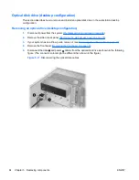
Optical bay filler or
optical drive
Chassis lock
Side access
panel
Airflow guide Front bezel
System board
Chassis lock
Side access
panel
Airflow guide Expansion
card hold
down clamp
or support
Expansion
cards or
DIMMs
Liquid
cooling
system (If
any)
Heatsink
(optional)
NOTE:
Z400s with 4 DIMM slots do not have an airflow guide.
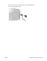
Cable lock (optional)
If a cable lock is installed on the workstation, remove it before servicing the workstation.
70
Chapter 5 Replacing components
ENWW