


S7999B SYSTEM DISPLAY
65-0283—2
54
Ethernet Setup
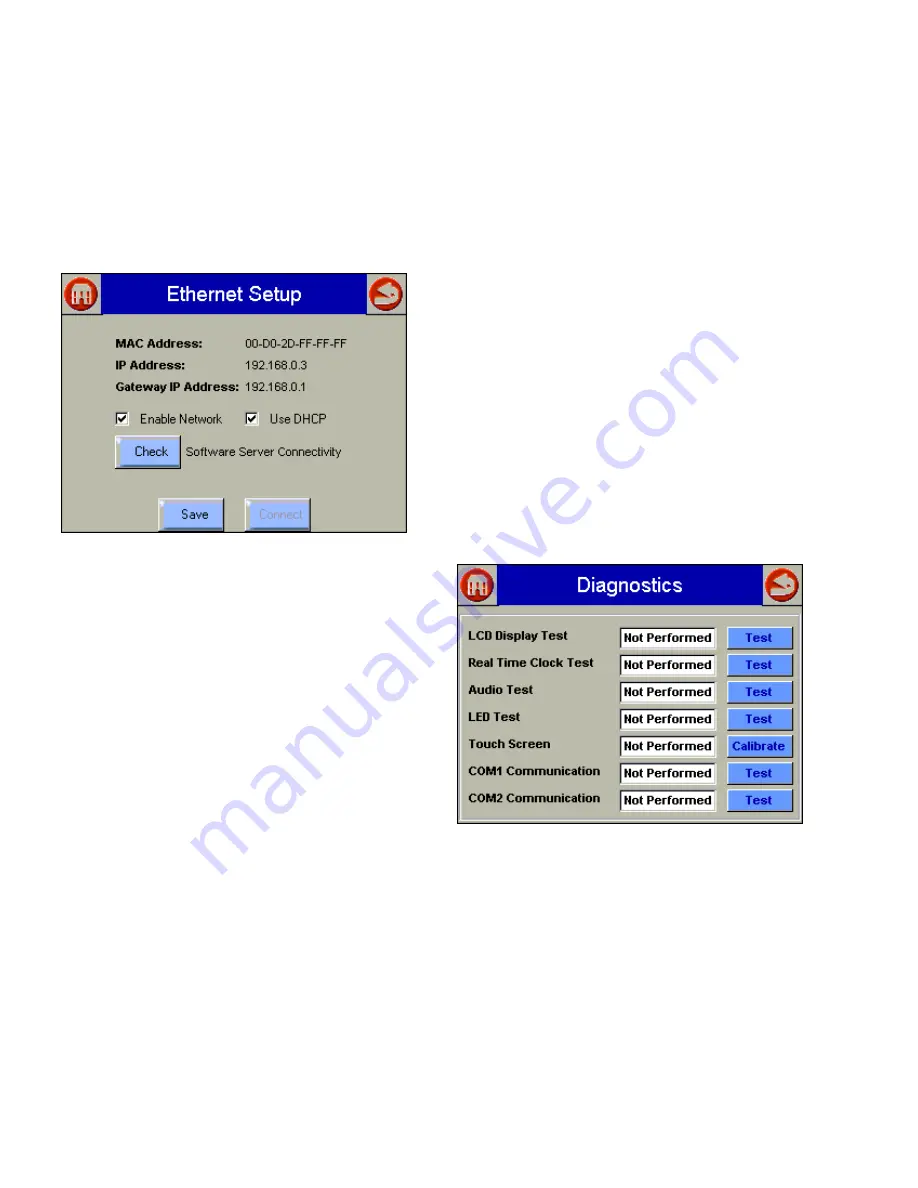
Ethernet Setup is used to enable Ethernet communications for
remote diagnostics, file transfers, and remote support, and is
not typically enabled (Fig. 115). This feature should remain
disabled unless directed to do so for remote troubleshooting.
Once the feature is enabled, the S7999B must be reset to
start it at power-up. The Ethernet interface can also be used
to transfer profile curve files to/from the S7999B over a local
intranet or the Internet.
Fig. 115. Ethernet Setup.
A Honeywell software server connectivity check can be
performed by selecting the Check button. This button is only
enabled when the Ethernet interface is enabled and active.
The connectivity check tries for 15 seconds to connect to the
Honeywell software server. Successful connection displays a
“CONNECTED” message on the screen. An unsuccessful
attempt displays “NOT CONNECTED.”
The MAC (Media Access Control) address is a hardware
address that uniquely identifies the S7999B on the network.
This information is likely only of interest to the network
administrator.
The IP (Internet Protocol) address is the address that the
S7999B has been assigned by the DHCP server in the local
network to use for others to access the S7999B. This address
is necessary for the remote user to identify the S7999B in an
FTP (File Transfer Protocol) application for transferring profile
curves. Like the MAC address, it is displayed for informational
purposes for the network administrator.
If the IP address has a private network designation
(192.x.x.x), remote access from outside the local network may
not be possible. Contact the network administrator for
assistance in this case. If the IP address is 255.255.255.255,
then no IP assignment has been made, and there is no
connection to the network. This possibility could be due to no
physical connection to an Ethernet network, or there is no
DHCP server present on the Ethernet network. Check with the
network administrator for assistance.
The Gateway IP address is displayed for informational
purposes for the network administrator. The gateway node
provides remote access for devices located off of the local
network to the S7999B.
The Enable Network checkbox specifies that the Ethernet
interface is on or not when the S7999B is powered up. The
selection must be saved to permanent storage (flash) with the
Save button for it take effect at boot time. This checkbox
should normally be disabled, and enabled when Ethernet
access to the S7999B is necessary. This interface must also
be enabled for the Software Server Connectivity check to
function properly (the Check button). If the Ethernet interface
is disabled, the check procedure fails.
The S7999B must be assigned an IP address by a DHCP
server for it to operate on the local network, so the Use DHCP
box should be checked. However, because the S7999B
requires this feature, it ignores the checkbox and always
regards it as checked. The checkbox is included for future
purposes when dynamic IP addressing isn’t required.
Diagnostics
The “Diagnostics” button displays a page (Fig. 116) that
permits some S7999B hardware diagnostics to be performed.
Normally, these diagnostics are applicable only for
factory testing purposes, but conditions may arise that
warrant this testing.
Fig. 116. S7999B Diagnostics.
NOTE:
COM 1 and COM 2 Communication testing will
always fail unless connected to a Honeywell factory
test fixture.
Each test is invoked by selecting the “Test” button next to the
diagnostic. The results of the diagnostic test (PASS/FAIL)
display in the text box next to the “Test” button.
Touch screen calibration should be performed when the
screen does not react correctly to an item touched/pushed on
the screen.


