S7999B SYSTEM DISPLAY
21
65-0283—2
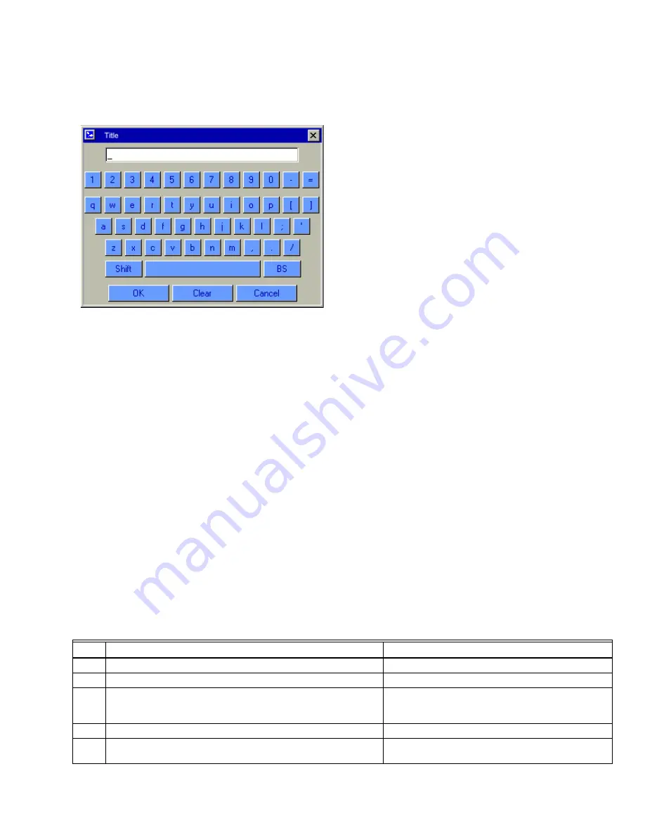
displays the current (or default) setting of the user input. The
user can append to this text, clear it to an empty value, or
backspace to remove characters at the end of the text.
Fig. 22. Keyboard.
A “Shift” key on the left side of the screen allows the user to
shift the keyboard between upper and lower case characters.
Touching the “Shift” button toggles the keyboard from one
mode to the other (continuous touching of the “Shift” button is
not required). An “OK” button on the bottom of the screen is
selected when the user is done entering (editing) the text
input. A “Cancel” button on the bottom of the screen allows
the user to ignore any text changes that have been made and
keep the original text value. Selecting either the “OK” button
or the “Cancel” button returns the user to the page displayed
prior to the keyboard page.
Power-up Validation
The Home page will appear and the POWER LED will be
blinking when the device is properly powered. Select the
Setup button to adjust the contrast as desired.
If the screen is dim, check pin 1 wiring connections.
NOTE: An Advanced Startup screen displays for five sec-
onds after power-up before the Home page displays.
This screen allows the user to upgrade the software
in the S7999B System Display (see Software
Upgrade Addendum) and should normally be
bypassed.
Communication Validation
Two LEDs exist for I/O traffic, one for the F/A Configuration
port and the other for the Modbus™ port.
1.
Make sure the LEDs are blinking.
2.
If the LEDs are not blinking:
a. Make sure the proper connections have been made
between R7999 ControLinks™ Control and the
S7999B F/A Config port.
b. Make sure the proper connections have been made
between the S7999B Modbus™ port and the first
S7810 Modbus™ module in the Modbus™ network.
c. See “Installing the Hardware” section for proper
wiring of the S7999B 9-pin Header Connections.
d. Make sure the ports are enabled on the User
Preferences page by using the Advanced Setup
page.
COMMISSIONING
Commissioning Process
Commissioning the R7999 using the S7999B System Display
requires the following general steps:
1.
Connecting the R7999 to the S7999B and logging into
the system with a password. This prevents
unauthorized users from modifying the modulation
curve.
2.
Specifying the base configuration: one or two fuels, with
or without FGR.
3.
Selecting system parameters such as Low Fire Hold.
4.
Specifying the characteristics of the actuators and
setting the valve/damper endpoints for those actuators.
5.
Creating a modulation curve (profile) for each fuel and
verifying it from maximum to minimum modulation.
(While you are commissioning the system, you must
monitor the burner operation with appropriate safety
instrumentation to verify the modulation curve.)
Commissioning Overview
The following table provides a step-by-step overview of how a
system is commissioned.
The Notes column in the table provide references to detailed
information when completing the more complex operations.
.
Table 4. Commissioning Overview.
Step
Action
Notes
1
On the Home page screen, select
Commission
.
2
On the WARNING screen, select
Commission
:
3.a.
Enter R7999 Commission password.
The S7999B requires you to enter the R7999
Commission password. The factory default password
is “password”.
3.b.
Set new password for new R7999 (factory state).
4
On the Commission Configuration screen, perform the following
steps:


