S7999B SYSTEM DISPLAY
31
65-0283—2
Auxiliary Sensor Configuration
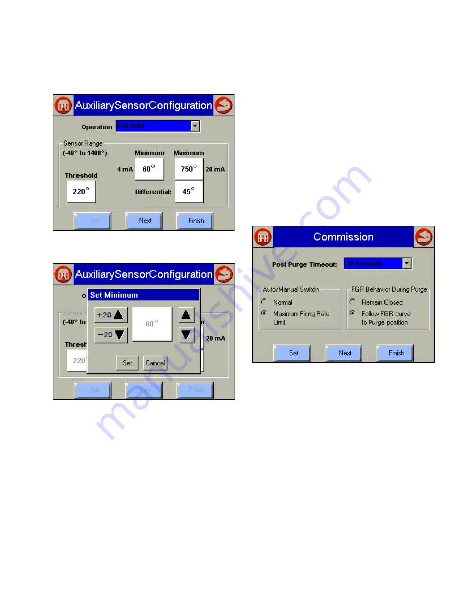
The first page that displays after the “System Configuration”
button is selected is shown in Fig. 41 and 42.
Fig. 41. Setting Auxiliary Sensor Parameters.
Fig. 42. Auxiliary Sensor Configuration—Set Minimum
Degrees.
Select an Operation from the dropdown list:
1.
Disabled means the input is ignored.
2.
Low Fire Hold—Selecting this option field enables an
algorithm that protects the boiler from thermal shock.
Upon successful progression to modulation, the
R7999 holds the burner at the lightoff point until the
auxiliary temperature input exceeds the programmed
threshold.
3.
FGR Hold—After successful progression to modulation,
the R7999 holds the FGR closed until the auxiliary
temperature input exceeds the programmed threshold.
4.
FGR and Low Fire Hold—Selecting this option enforces
both of the above actions.
a.
Max (20 mA)
—This field lets you set the maximum
sensing range of the transducer. The maximum
value must be between -40°F and 1400°F.
b.
Min (4 mA)
—This field lets you set the minimum
sensing range of the transducer. The minimum must
be less than the maximum by at least 100°F.
c.
Threshold
—This field lets you set the threshold
temperature at which you want the low fire hold or
FGR hold or Low Fire and FGR hold to be released.
The threshold temperature must be less than the
maximum and greater than the minimum.
d.
Differential
—This field lets you set the differential
temperature at which the system will revert to a hold
condition. The threshold must be set lower than the
threshold but greater than the minimum.
Remember to press the Set button before moving to a
different page.
When the “Next” button is selected, the following figure
displays.
Fig. 43. Miscellaneous Commissioning Parameters.
Controller timing: Postpurge Timeout
—Use the dropdown
list to select how long the system should wait at the postpurge
position once the postpurge state has been detected. It is
important that the postpurge timeout time be at least as long
as the burner control time, especially when the air damper is
configured to close while in standby.
Auto/Manual Switch
a. Select either Normal or Maximum Firing Rate Limit.
b. When the Maximum Firing Rate Limit is selected,
the R7999 (when in auto mode) reads the value of
the manual potentiometer input and does not allow
modulation beyond its interpreted value. The
manual potentiometer input equates 0 to 500 ohms
as a 4 mA firing rate input and 4500 ohm or greater
as a 20 mA input; all other values are determined by
linear interpolation. The behavior during manual
switch setting is not affected, i.e., the firing rate input
is derived directly from the potentiometer value and
the controller mA input is ignored.


