S7999B SYSTEM DISPLAY
65-0283—2
26
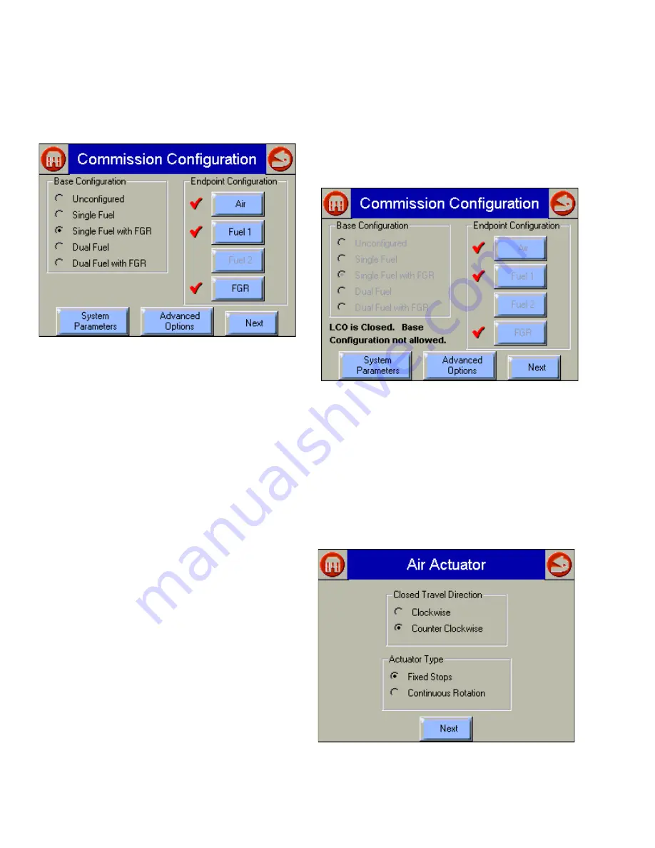
The user can choose to end the commissioning process
before everything is finished, and, if so, this page has the
appearance of the following two figures (Fig. 26 and 27), to
indicate where the user left off.
Fig. 26. Commission Configuration—uncompleted
commissioning view.
NOTE: Clicking the Home or Back or button will exit this
screen and display the Home page.
NOTE: Actuators that have completed their configuration
have a checkmark next to their button.
You must perform the following actions from this screen:
1.
Select base configuration for the system:
a.
Base Configuration
(1)
Unconfigured
—This is the initial (default)
option. You can select this option to erase the
current configuration and reset to factory
configuration.
(2)
Single Fuel
—Select if you want to configure
only one fuel actuator and one air actuator.
(3)
Single Fuel with FGR
—Select if you want to
configure a fuel actuator, an air actuator, and an
FGR actuator.
(4)
Dual Fuel
—Select if you want to configure two
fuel actuators and one air actuator.
(5)
Dual Fuel with FGR
—Select if you want to
configure two fuel actuators, one air actuator,
and an FGR actuator.
2.
Select and configure all actuators within the base
configuration:
b.
Air
Fuel1
Fuel 2
FGR
(1) Press a button to configure the actuator. (If you
selected ‘Single Fuel’ or ‘Single Fuel with FGR’
in the Base Configuration, the Fuel 2 button is
not displayed. If you selected ‘Single Fuel’ or
‘Dual Fuel’ in the Base Configuration, the
FGR
button is not displayed.) When you press a
button, the
Set Actuator Endpoints
screen is
displayed. When the actuator has been
configured, a checkmark is displayed next to the
appropriate button. See Fig. 26.
3.
Go to the System Parameters screens to set system
parameters or view the default system parameters (If
necessary).
4.
Press the Next button to configure a ControLinks™
curve.
5.
Press Advanced Options Load Curve button to load and
configure a pre-existing ControLinks™ curve.
Fig. 27. Commissioning Configuration—completed
commissioning view.
Actuator Configuration
Selecting an actuator button displays a page like Fig. 28.
The direction that the actuator travels when it moves to its
closed position, and whether the actuator moves in fixed stops
or continuously rotates until it is told to stop, is selected on this
screen. Press the Next button when the settings are correct
for the actuator to advance to the next screen.
Fig. 28. Selecting Air Actuator type and travel direction.


